The core distinction comes down to one thing: compression direction. Axial seals are squeezed along the shaft axis; radial seals are squeezed across the radius. That single mechanical difference determines groove geometry, surface finish requirements, pressure handling capability, and whether a seal survives in motion or fails within hours.
This guide breaks down how each seal type works, where each performs best, and how to match the right configuration to your specific application—whether you're sealing a pipeline flange or a reciprocating hydraulic cylinder rod.
Key Takeaways
- Axial seals compress the sealing element top-to-bottom (along the axis); radial seals compress inner-to-outer diameter (across the radius)
- Axial seals suit static face/flange joints; radial seals handle both static and dynamic (reciprocating, rotating, oscillating) environments
- Radial seals are preferred for high-pressure dynamic systems; axial seals offer simpler installation for pipeline and face-joint sealing
- Compound selection (NBR, FKM, EPDM) must match your specific fluid, temperature, and pressure conditions for either seal type
- The right choice comes down to motion type, pressure direction, and assembly geometry — not a blanket preference for one over the other
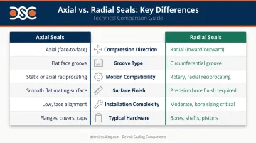
Axial Seals vs Radial Seals: Quick Comparison
| Factor | Axial Seals | Radial Seals |
|---|---|---|
| Compression direction | Along the shaft axis (top-to-bottom) | Across the radius (ID to OD) |
| Groove type | Axial/face groove | Circumferential groove |
| Motion compatibility | Static; rotary axial variants for high-speed rotation | Static and dynamic (reciprocating, rotating, oscillating) |
| Surface finish requirement | Less demanding | Dynamic types: Ra ≤ 0.4 μm (Trelleborg); Ra 0.2–0.8 μm (SKF) |
| Installation complexity | Lower—simpler groove geometry | Higher for dynamic types—tight bore and shaft tolerances |
| Typical hardware | Flange screw connections, end caps, inspection covers | Piston/bore assemblies, rotating shaft assemblies, hydraulic cylinders |
| Initial compression (O-ring) | 13%–36% for static axial | 10%–35% for static radial |
Source: Trelleborg O-Rings & Back-up Rings catalog, June 2024
O-rings can function in either orientation. The groove geometry and pressure direction determine the seal type: axial for flanges, plates, and caps; radial for bushings, covers, cylinders, and rods. The O-ring itself is the same either way.
What Are Axial Seals?
An axial seal is compressed between two flat mating faces—the compressive force runs parallel to the shaft axis, squeezing the top and bottom of the seal's cross-section. Common examples include O-rings seated in face grooves on flanges, flat gaskets between pipe end caps, and inspection port covers.
Pressure Direction and Groove Design
Groove design must account for the expected pressure direction. The sealing element contacts either the inner or outer edge of the groove depending on which side pressure acts, and that contact point directly determines leak prevention effectiveness. Getting the pressure direction wrong relative to groove geometry will cause early seal failure.
Rotary Axial Seals: The Dynamic Variant
Standard axial seals are static, but a specialized subtype extends this design into dynamic rotating applications: rotary axial seals like the Trelleborg GAMMA Seal and SKF V-ring seals. The seal lip presses perpendicularly against a stationary counter-face, and centrifugal force reduces lip contact pressure at higher speeds, in some configurations creating a near-non-contacting operation that minimizes friction.
Detroit Sealing Components stocks V-Seals as an axial sealing solution for rotating shafts. Manufactured in NBR and FKM, these all-rubber seals mount directly onto the shaft and create a face seal that retains lubricants while excluding contaminants.
Key operational benefits of axial seals:
- Simpler installation compared to dynamic radial seals—less precision required on mating surfaces
- Effective in static face-joint applications with infrequent disassembly
- Rotary axial variants provide combined sealing and contamination deflection at high shaft speeds
- Lower ongoing maintenance cost due to straightforward replacement geometry
Where Axial Seals Are Used
Static applications: Pipeline flange connections, inspection port covers, end-cap face joints, and manifold assemblies where no relative motion occurs between sealed surfaces.
Dynamic/rotary applications: Industrial gearboxes, electric motors, water pumps, and heavy equipment operating in contaminated or wet environments—anywhere high-speed shaft rotation is present and contamination exclusion matters.
What Are Radial Seals?
A radial seal is compressed between two concentric cylindrical surfaces—squeezed from the inside diameter to the outside diameter. It seats in a circumferential groove on a bore or piston, and the sealing force acts perpendicular to the shaft axis.
Static vs. Dynamic Radial Seals
These two subtypes have meaningfully different performance requirements:
Static radial seals are used where mating surfaces don't move relative to each other. They're more forgiving—wider gap tolerance, rougher bore finish, higher pressure differential handling. Applications include pipe connectors, valve bodies, and bore-to-shaft joints in fluid handling equipment. For both types, Trelleborg recommends not exceeding 85% groove fill to account for thermal expansion, volume swell, and tolerance stack-up.
Dynamic radial seals operate under continuous relative motion—reciprocating rod seals in hydraulic cylinders, rotating shaft seals in pumps and motors. Surface finish requirements are strict: SKF specifies counterface roughness between Ra 0.2 and 0.8 μm, while Trelleborg's dynamic radial guidance is tighter still at Rz ≤ 2.5 μm and Ra ≤ 0.4 μm.
Compound Selection for Radial Seals
Dynamic radial seals experience continuous contact stress and thermal cycling, making compound matching critical. According to Trelleborg's catalog data:
- NBR (nitrile): Mineral-based oils and greases; –30°C to +100°C operating range
- FKM (fluorocarbon/Viton-type): Excellent ozone, weathering, and aging resistance; –20°C to +200°C
- EPDM: Listed as a common O-ring elastomer; consult compound data for specific fluid compatibility
- HNBR, FFKM, FEPM: Higher-performance options for aggressive environments, including oil & gas downhole applications
When standard compounds fall short, DSC offers specialty materials including FFKM, FEPM, and FVMQ, with custom compound development supported by an ISO 17025 accredited lab.
Where Radial Seals Are Used
Core applications:
- Hydraulic and pneumatic cylinder rod and piston seals
- Rotating shaft assemblies in pumps and motors
- Static sealing in manifold assemblies and valve bodies
- Clean fluid handling in food and beverage processing (hygienic elastomeric seal designs per EHEDG 2023 guidelines)
Industries served: Automotive, oil & gas, agriculture and construction (hydraulic cylinder seals in heavy equipment), food and beverage, general industry, and semiconductor applications where contamination prevention in static radial configurations is critical.
Axial vs Radial Seals: Which Is Right for Your Application?
The selection framework is straightforward once you identify three things: motion type, pressure direction, and joint geometry.
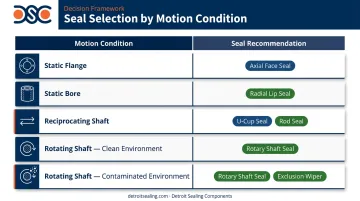
Step 1 — Identify Motion Type
| Motion condition | Seal recommendation |
|---|---|
| Completely static, face/flange joint | Axial seal (O-ring or flat gasket) |
| Completely static, bore/piston geometry | Static radial seal |
| Reciprocating (hydraulic rod, pneumatic actuator) | Dynamic radial seal with wiper and backup ring pairing |
| Rotating shaft, clean environment | Radial shaft seal |
| Rotating shaft, contaminated/wet environment | Rotary axial seal (V-ring or GAMMA-type) |
Step 2 — Confirm Pressure Direction
- Pressure acting parallel to the shaft axis and loading a face joint → axial seal
- Pressure acting radially (outward or inward across a bore) → radial seal
- Misalignment between pressure direction and seal orientation is a leading cause of early seal failure—this step is not optional
Step 3 — Match Geometry and Compound
Once motion type and pressure direction are confirmed, groove geometry and compound selection complete the specification. Key factors:
- Fluid medium (petroleum-based, aqueous, chemical)
- Temperature range (operating minimum and maximum)
- Pressure differential (static vs. cyclic)
- Surface finish capability of the mating hardware (critical for dynamic radial seals)
Getting these factors right often requires application-specific expertise. DSC's technical team works through this selection process directly with customers, using CAD and finite element analysis to validate seal geometry and behavior before production quantities are committed.
For material verification, DSC's ISO 17025 accredited lab can bench-test compounds under customer-defined conditions to confirm performance against actual application parameters.
Real-World Application Scenarios
Scenario 1: Static Pipeline Flange — Axial Seal
A process engineer specifying a high-volume water distribution pipeline needs to seal a bolted flange connection. The joint is static—no relative motion between flanged faces—and pressure acts axially, loading the face seal.
An axial O-ring seated in a face groove is the correct geometry. As Trelleborg's catalog confirms, axial O-ring static seals are standard for flanges, plates, and caps. Flanged gasket applications of this type fall under ASME B16.20 (metallic gaskets) and EN 1514-1:2024 (non-metallic flat gaskets for PN flanges up to DN 4000).
Compound selection here depends on the fluid: EPDM for potable water, FKM for treated or chemically aggressive media. Proper groove fill (not exceeding 85%) and correct initial compression (13%–36% for axial static) ensure reliable, low-maintenance performance across infrequent disassembly cycles.
Scenario 2: Heavy Equipment Hydraulic Cylinder — Dynamic Radial Seal
A construction equipment manufacturer needs to seal a hydraulic cylinder rod subjected to constant reciprocating motion and exposure to abrasive debris from earthmoving operations.
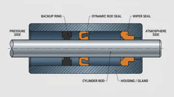
As Hallite notes, contaminant ingress is one of the primary causes of premature hydraulic seal failure. The standard configuration for this application combines three components:
- Dynamic radial rod seal — handles pressure and reciprocating motion
- Wiper seal (UA2, UA4) — excludes abrasive debris before it reaches the rod seal
- Backup ring — prevents seal extrusion under high-pressure cycling
Surface finish on the rod and bore must meet dynamic radial specifications—Ra ≤ 0.4 μm on the dynamic mating surface per Trelleborg guidance. Extrusion gap management is just as important: a 2024 case documented in Sealing & Contamination Control Tips shows seal failure occurring even with the correct compound when extrusion gap tolerances aren't controlled.
DSC stocks rod and piston seals (UF1, UF2, UF4, UH1, UH2) and backup rings in 90-durometer NBR and FKM—providing the complete sealing system for this application.
Across both scenarios, the pattern is consistent: geometry drives the selection, compound determines the lifespan. Getting either wrong is expensive. Contact Detroit Sealing Components to work through your specific axial or radial seal configuration—with access to hundreds of compounds and ISO 17025 lab validation before you commit to production.
Frequently Asked Questions
What is the difference between axial and radial sealing?
The core difference is compression direction. Axial seals compress the sealing element along the shaft axis (squeezed between two flat mating faces) and are used in flange and face joints. Radial seals compress from inner to outer diameter and are used in bore/piston assemblies or around rotating shafts.
What are the three types of mechanical seals?
The three commonly recognized types are contacting (pusher and non-pusher designs), non-contacting (gas-lubricated or liquid-film), and cartridge seals. Axial and radial describe installation orientation, not seal classification — the same O-ring can function in either, depending on groove design.
Can axial seals be used in dynamic applications?
Standard axial seals are designed for static applications. Rotary axial seals—such as V-rings and GAMMA-type seals—are engineered for high-speed shaft rotation, using centrifugal force to reduce lip contact pressure and exclude contaminants, making them suitable for gearboxes, motors, and pumps.
Which seal type is easier to install?
Axial seals are generally easier to install. They require less precision in bore finish and gap tolerancing than dynamic radial seals, which demand tight machined surface finishes (Ra ≤ 0.4 μm) and exact groove dimensions to prevent extrusion or premature wear.
What materials are commonly used for axial and radial seals?
Both types draw from the same elastomer families: NBR for petroleum-based fluids, FKM for high-temperature applications, EPDM for aqueous media, and specialty compounds like HNBR and FFKM for aggressive environments. Compound selection must match fluid chemistry, temperature range, and pressure — not just the seal geometry.
What happens if I use the wrong seal type?
Common consequences include premature extrusion (seal material forced into the clearance gap), leakage under pressure, accelerated wear in dynamic applications, and in critical systems, unplanned equipment shutdown. The chosen seal configuration must align with the application's motion type, pressure direction, and groove geometry — all three.