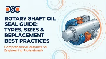
Introduction
Equipment failure and costly downtime often trace back to a single component: the rotary shaft oil seal. Research shows that seal failure is rarely a defect of the component itself but rather a result of improper specification or installation. For maintenance professionals and engineers, understanding how to select, size, and replace these critical sealing devices directly impacts equipment reliability and operational costs.
The sections below walk through seal design types, material selection, sizing, and installation techniques that prevent premature failure. Whether you're sourcing a replacement or specifying a seal for a new application, this guide gives you the technical grounding to get it right the first time.
Key Takeaways
- Rotary shaft oil seals prevent lubricant loss and contamination through a sealing lip, spring element, and outer case
- Material selection (NBR, FKM, PTFE) drives temperature range, chemical compatibility, and service life
- Proper sizing requires measuring shaft diameter, housing bore, and width to specific tolerances
- Installation errors cause most early failures—shaft preparation and proper tools are essential
- Standard seals run $5–$50; specialty designs reach $50–$500+, with replacement taking 1–4 hours
What Are Rotary Shaft Oil Seals
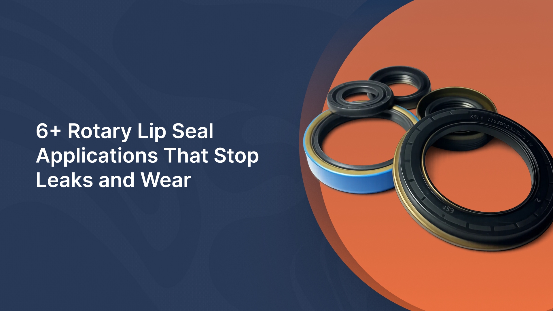
Rotary shaft oil seals are dynamic sealing devices engineered to prevent lubricant leakage and contamination ingress around rotating shafts. These precision components maintain the critical barrier between internal lubricants and external contaminants in motors, gearboxes, pumps, and similar rotating equipment.
Core Components
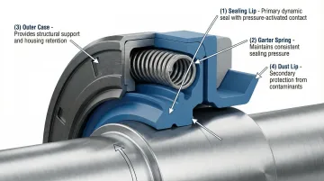
Every rotary shaft seal consists of three essential elements working together:
Sealing Lip: The flexible elastomeric or thermoplastic element that contacts the shaft directly. Modern lips include molded hydrodynamic grooves that actively pump oil back into the system rather than letting it escape.
Garter Spring: A coiled carbon or stainless steel spring seated above the lip that delivers constant radial load — keeping the lip against the shaft through wear, compression set, and minor runout.
Outer Case: A sheet steel or rubber-covered metal shell that locks the seal into the housing bore via interference fit, blocking static leakage at the outer diameter.
Primary Functions
Rotary shaft seals serve two critical purposes:
- Retain lubricants inside equipment, preventing costly fluid loss and maintaining proper lubrication
- Exclude contaminants including dirt, moisture, and particulates that accelerate wear and cause premature equipment failure
In harsher operating conditions, a third element comes into play: an auxiliary dust lip positioned outboard of the primary lip. This non-spring-loaded secondary lip intercepts external pollutants before they reach the primary sealing interface.
Types of Rotary Shaft Oil Seals
Single Lip vs. Dual Lip Designs
Single lip seals represent the standard configuration for most applications where lubricant retention is the primary concern. These seals feature one spring-loaded sealing lip and work effectively in clean environments or where contamination risk is minimal.
Dual lip seals add a secondary dust lip for applications facing harsh conditions or when separating two different fluids. The additional lip provides an extra barrier against contaminants entering the sealing zone, extending seal life in dirty environments like construction equipment, agricultural machinery, or mining operations.
Standard Design Codes (DIN 3760/ISO 6194)
International standards define seal construction through specific type codes. Understanding these designations ensures proper selection:
| Type Code | Construction | Best For | Key Advantage |
|---|---|---|---|
| Type R/A | Rubber-covered outer case with spring | Retrofit applications, split housings | Easiest installation; tolerates minor housing imperfections |
| Type M/B | Metal case with spring | OEM equipment, high-volume production | Cost-effective; requires H8 bore tolerance and smooth finish |
| Type RST/AS | Rubber-covered with dust lip | Contaminated environments | Type A benefits plus contamination protection |
| Type MST/BS | Metal case with dust lip | Dirty applications requiring cost efficiency | Type B benefits plus dust exclusion |
| Type GV/C | Heavy-duty double metal case | Large diameters (100mm+), demanding applications | Enhanced rigidity and dimensional stability |
Specialty Oil Seal Types
Three specialty types address conditions where standard rubber lip seals fall short:
- PTFE Lip Seals — Handle temperatures from -90°C to +260°C, pressures up to 10 bar, and chemically aggressive environments. They require harder shaft surfaces (58-62 HRC) and finer finishes (Ra 0.1-0.4 µm) than elastomeric seals.
- Cassette Seals — Pre-assembled units integrating the seal, bearing, and housing in one component. Common in wheel-end and heavy-duty applications where installation simplicity and contamination protection are priorities.
- Fabric-Reinforced Rubber Seals — Split-design seals installable without disassembling equipment, useful for hard-to-access shafts or when minimizing downtime is critical.
Oil Seal Materials Guide
Material selection determines seal performance, service life, and total cost of ownership. Choosing the wrong material leads to rapid failure regardless of proper installation.
Nitrile Rubber (NBR) — The Industry Standard
NBR delivers excellent resistance to mineral oils, greases, and hydraulic fluids at temperatures from -35°C to 100°C. This economical choice handles shaft speeds up to 10-12 m/s on larger diameters and remains the default selection for general industrial applications.
Limitations:
- Poor resistance to synthetic oils (especially glycol-based fluids)
- Degrades rapidly when exposed to acids, solvents, or ozone
- Maximum continuous temperature of 80°C in synthetic oil applications
Fluoroelastomer (FKM/Viton) — High Performance
FKM extends the operating envelope significantly: -15°C to 180°C temperature range, compatibility with synthetic oils, acids, and bases, and shaft speeds up to 35-38 m/s. FKM typically provides 2-3x longer service life than NBR. That longevity offsets the higher upfront cost through fewer replacements and less equipment downtime.
When to specify FKM:
- Operating temperatures exceed 100°C
- Synthetic lubricants or hydraulic fluids are used
- Chemical exposure includes acids, fuels, or aggressive additives
- High shaft speeds require superior heat resistance
PTFE (Teflon) — Extreme Conditions
PTFE offers unmatched chemical resistance, ultra-low friction, and extreme temperature capability (-80°C to 200°C). FDA-compliant PTFE grades suit pharmaceutical and food processing applications where contamination is unacceptable.
Requirements:
- Shaft hardness: 58-62 HRC minimum
- Surface finish: Ra 0.1-0.4 µm (tighter than typical elastomer specifications)
- Proper installation technique (PTFE is less forgiving of installation errors)
Other Materials: EPDM, Silicone (VMQ), and Polyacrylate
Three additional materials cover niche but important use cases — each with hard limits that disqualify them from general-purpose applications.
EPDM: Excellent for hot water, steam, and UV exposure (-50°C to 150°C) but not recommended for petroleum oils.
Silicone (VMQ): Extreme temperature range (-60°C to +200°C) and FDA compatibility make silicone attractive for specific applications, but poor abrasion resistance limits use in dynamic sealing with contaminated oils.
Polyacrylate (ACM): Resists EP (extreme pressure) additives and ozone better than NBR with temperatures to 150°C, though not suitable for water, acids, or low-temperature applications.
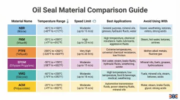
Material Comparison Table
| Material | Temp Range | Speed Limit | Best Applications | Avoid Using With |
|---|---|---|---|---|
| NBR | -40°C to +100°C | ~12 m/s | Mineral oils, general hydraulics | Synthetic oils, acids, ozone |
| FKM | -20°C to +200°C | ~38 m/s | High temp, synthetic oils, chemicals | Esters, ketones, hot steam |
| PTFE | -80°C to +250°C | 30-100 m/s | Extreme chemicals, dry running | Standard shaft finishes |
| EPDM | -50°C to +150°C | N/A | Hot water, steam, polar solvents | Petroleum oils |
| VMQ | -60°C to +200°C | ~38 m/s | Extreme temps, FDA applications | Contaminated oils (poor wear) |
| ACM | -40°C to +150°C | ~22 m/s | EP additives, ozone resistance | Water, acids, cold environments |
When standard compounds don't meet your application requirements, DSC's ISO 17025 accredited lab and ISO 9001:2015 certified quality system can develop and validate custom materials across all rubber types — a practical option for demanding or unusual service conditions.
How to Measure and Size Oil Seals
Understanding Oil Seal Dimensions
Rotary shaft seals follow a standard sizing format: shaft diameter × bore (housing) diameter × width. For example, 25×40×7 mm indicates a 25mm shaft, 40mm housing bore, and 7mm axial width.
Measuring existing seals:
- Shaft diameter (inner): Measure the seal's inner diameter where it contacts the shaft
- Housing bore (outer): Measure the seal's outer diameter
- Axial width: Measure the seal's thickness from face to face
Critical measurement tips:
- Use calipers or micrometers for accuracy within 0.1mm
- Measure at the sealing surfaces, not worn areas
- Account for wear on used seals—the original shaft diameter may be smaller than a worn seal's inner diameter
Shaft and Bore Tolerances
Precision matters. Adherence to ISO h11 shaft tolerances and H8 housing bore tolerances prevents leakage and excessive wear.
Shaft requirements:
- Tolerance: ISO h11 (standard for elastomer lips)
- Surface finish: Ra 0.2-0.8 µm for NBR/FKM; Ra 0.2-0.4 µm for PTFE
- Hardness: Minimum 45 HRC (standard); 55+ HRC for high-speed or contaminated environments; 58-62 HRC for PTFE seals
Housing bore requirements:
- Tolerance: ISO H8 ensures proper interference fit without installation damage
- Surface condition: Clean, smooth, free of nicks or burrs
Deviations from these specifications accelerate failure—too rough causes abrasion, too smooth starves the sealing interface of lubrication.
Standard Sizes vs. Custom Solutions
Metric standards (ISO 6194/DIN 3760) cover most common applications with readily available stock sizes. Standard sizes offer immediate availability and lower cost.
When custom sizes are necessary:
- Non-standard or vintage equipment with unique dimensions
- Space constraints requiring modified seal geometry
- Specialized performance requirements exceeding standard seal capabilities
For situations like these, Detroit Sealing Components stocks over 8,000 tooled articles, with new sizes added monthly. When an application falls outside standard ranges, DSC uses computer-aided design and finite element analysis to validate custom seal geometry before production — reducing lead time and avoiding costly trial-and-error.
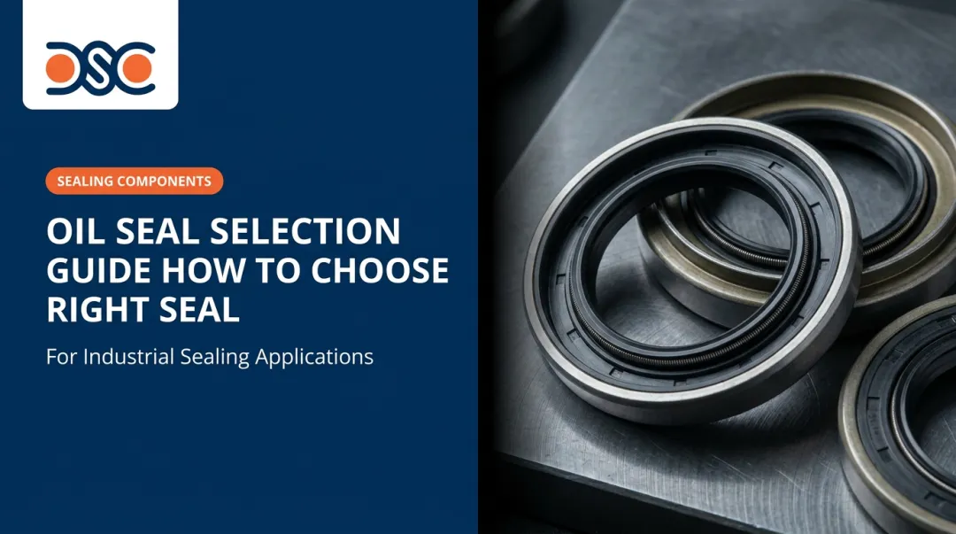
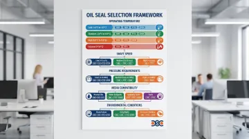
Oil Seal Selection Criteria
Matching seals to application conditions requires evaluating multiple factors simultaneously. Use this decision framework:
Operating Temperature:
- Below -20°C: Consider FKM or PTFE
- -20°C to +100°C: NBR suitable
- +100°C to +180°C: FKM required
- Above +180°C: PTFE necessary
Shaft Speed:
- Up to 12 m/s: NBR acceptable
- 12-38 m/s: FKM recommended
- Above 38 m/s: PTFE or specialized high-speed designs
Pressure Requirements:
- Unpressurized or <0.05 MPa: Standard seals sufficient
- 0.05-1.0 MPa: Specialized pressure seal designs
- Above 1.0 MPa: PTFE or heavy-duty pressure seals required
Media Compatibility:
- Mineral oils/greases: NBR cost-effective
- Synthetic oils: FKM required
- Aggressive chemicals: PTFE necessary
- Hot water/steam: EPDM specified
Environmental Conditions:
- Clean environments: Single lip adequate
- Contaminated/dusty: Dual lip with dust exclusion
- Outdoor/mobile equipment: Rubber-covered case (Type A/AS)
These performance limits don't operate in isolation—high shaft speeds generate heat that directly reduces a seal's pressure-handling capability, so borderline conditions across multiple factors compound the risk of premature failure. When your application pushes against more than one of these thresholds, application-specific engineering analysis is worth the investment. Detroit Sealing Components' technical team works through exactly these scenarios, using finite element analysis to model seal behavior under combined load conditions and recommend the right material and design before a failure occurs.
Replacement Best Practices
When to Replace Oil Seals
Failure indicators requiring immediate replacement:
- Visible leakage at the shaft interface
- Excessive shaft wear or grooving at the seal contact area
- Hardened, cracked, or torn seal lips
- Contamination visible in lubricant (indicates seal is no longer excluding dirt)
Preventive replacement strategy: Replace seals during scheduled maintenance even if they appear functional. Emergency repairs cost far more — unplanned downtime, expedited parts, and secondary bearing damage add up quickly.
Best practice: Replace seals whenever shafts or bearings are serviced. The labor cost to access the seal location often exceeds the seal's cost, making replacement during existing maintenance intervals economically logical.
Pre-Installation Preparation
Proper preparation eliminates the most common causes of installation-related failures.
Shaft inspection and preparation:
- Check for burrs, nicks, scratches, or excessive wear—any imperfection can damage the seal lip during installation
- Verify shaft diameter meets tolerance specifications (h11)
- Confirm surface finish (Ra 0.2-0.8 µm for elastomers)
- Polish out minor imperfections; replace severely worn shafts
Housing inspection:
- Clean bore thoroughly, removing old seal residue, dirt, and corrosion
- Verify bore is undamaged and meets H8 tolerance
- Check for proper lead-in chamfer (15-30° recommended)
Before installation, lubricate the seal lip, shaft, and bore with compatible grease. This prevents dry running at startup and lets the seal seat correctly.
Cover keyways, threads, splines, and shaft ends with an installation sleeve or tape before sliding the seal on. Sharp edges destroy seal lips instantly.
Proper Installation Techniques
Most immediate seal failures trace back to installation errors.
Correct orientation: The spring side must face the fluid being sealed. Installing a seal backwards guarantees immediate leakage.
Use proper tools:
- Seal drivers or installation sleeves distribute force evenly
- Arbor press applies controlled, perpendicular force
- Never hammer directly on the seal—this damages lips, distorts cases, and displaces springs
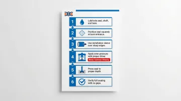
Installation procedure:
- Lubricate seal, shaft, and bore
- Position seal squarely at bore entrance
- Use installation sleeve over shaft if sharp edges present
- Apply even pressure with proper driver
- Press seal to proper depth (typically flush with housing face or to specified depth)
- Verify seal is fully seated with no gaps
Keep the seal square: Enter the bore perpendicular to the shaft axis. Even slight cocking causes immediate leakage and lip damage.
Shaft Preparation and Repair
Surface finish requirements:
| Seal Type | Typical Ra | Optimal Ra |
|---|---|---|
| Elastomeric | 0.4–0.8 µm | 0.2–0.5 µm |
| PTFE | 0.2–0.4 µm | 0.2–0.4 µm |
When wear is excessive, shaft repair sleeves are a practical fix. They press over the worn area and deliver a fresh sealing surface — no shaft replacement or re-machining required.
To improve finish, polish lightly with 400-600 grit abrasive cloth in the axial direction only. Circumferential scratches create leak paths along the seal lip.
Post-Installation Verification
Immediate checks:
- Confirm proper orientation (spring toward fluid)
- Check for installation damage to seal lip or case
- Verify seal is fully seated with no visible gaps between seal and housing
Initial operation:
- Run equipment at reduced speed and load for the first 30-60 minutes when possible
- Monitor for leaks during the first hours — this is when most installation issues surface
Follow-up monitoring:
- Check lubricant levels regularly after replacement
- Inspect for leakage at the first scheduled maintenance interval
- Document seal type, installation date, and operating conditions for maintenance records
Frequently Asked Questions
What are the different types of oil seals?
The main types include single lip seals (standard for lubricant retention), dual lip seals (with additional dust lip for contaminated environments), and spring-loaded designs (providing consistent radial force). Specialty types include PTFE lip seals for extreme temperatures and chemicals, and cassette seals—complete assemblies with integrated bearings for heavy-duty applications.
What is the difference between SC, TC and TG oil seals?
These are manufacturer-specific codes without universal standardization. Generally, SC indicates spring-loaded rubber lip seals, TC indicates spring-loaded dual lip designs, and TG references PTFE lip seals. Always verify the specific manufacturer's catalog, as these codes may map to different DIN/ISO types depending on the producer.
How do you identify oil seals?
Identify seals by measuring three dimensions: shaft diameter (inner), housing bore (outer), and axial width. Examine the lip design—single or dual, material color (black typically indicates NBR, brown/green suggests FKM). Check the metal case for stamped markings or codes indicating manufacturer and specifications.
How do you measure oil seals?
Use calipers to measure: (1) inner diameter at the sealing lip (shaft size), (2) outer diameter of the case (bore size), and (3) axial width from face to face. Measure at the sealing surfaces, not worn areas. Record measurements in the format shaft × bore × width (e.g., 30×47×7 mm).
How much do oil seals cost to fix?
Standard seals range from $5–50, while specialty seals (PTFE, cassette designs) cost $50–500+. Labor runs 1–4 hours for accessible external seals, but internal seals requiring gearbox disassembly can exceed 8 hours. Total replacement costs range from $50 to $1,000+ including parts and labor.
How long do rotary shaft seals last?
Typical service life ranges from 2,000–10,000 operating hours depending on application severity, material selection, installation quality, and operating conditions. Properly selected FKM seals in controlled environments can exceed 20,000 hours, while NBR seals in harsh conditions may fail within 1,000 hours.
Need expert guidance on seal selection or custom solutions? Detroit Sealing Components' technical team provides application-specific recommendations backed by decades of sealing experience. Contact DSC at +1 313-887-4695 or reach their Plymouth, Michigan team for sealing solutions ranging from standard components to custom-engineered designs.