Research on elastomeric seal aging confirms that thermal exposure accelerates multiple simultaneous degradation mechanisms in compressed O-rings — meaning a seal that looks intact can have already lost the sealing force needed to prevent leakage. Without structured integrity testing across the actual thermal profile of your application, material selection is informed guessing at best.
This article covers the primary testing methods, how to structure a validation protocol, and what "passing" actually means for seals in thermally demanding service.
Key Takeaways
- O-ring integrity testing for thermal cycling verifies that seals hold their force and dimensions across repeated temperature extremes
- Core test methods: compression set (ASTM D395), thermal shock/cycling chamber, pressure decay, helium leak, and low-temperature flexibility (ASTM D2137)
- Each test targets a distinct failure mode — permanent deformation, cracking, leakage, or brittleness
- Material choice (Nitrile, FKM, Silicone, EPDM, FFKM) determines which tests apply and what pass/fail thresholds to use
- Qualification always requires a multi-method test protocol, not a single pass/fail check
What Is O-Ring Seal Integrity Testing for Thermal Cycling?
O-ring seal integrity testing for thermal cycling covers the standardized and application-specific methods used to verify that an elastomeric seal performs reliably under repeated heating and cooling. Specifically, it confirms that the seal maintains adequate sealing force, dimensional stability, and leak resistance across its full operating temperature range.
The applications span a wide range:
- Automotive drivetrains, engine cooling, and HVAC systems
- Aerospace hydraulics and fuel delivery
- Oil and gas downhole equipment
- Semiconductor processing chambers
- Renewable energy systems exposed to outdoor temperature swings
Testing serves two distinct goals:
- Pre-deployment qualification — confirming a material and compound will survive the application before it goes into service
- Failure diagnosis — determining whether thermal degradation caused an in-service seal failure and at what point in the lifecycle it began
The methods used overlap significantly between both goals. The difference is in starting point: qualification testing runs planned cycle counts against defined acceptance criteria, while failure analysis typically begins with dimensional and hardness measurement to establish what changed and when.
Why Thermal Cycling Makes O-Ring Testing Non-Negotiable
The Physical Mechanism
Every thermal cycle puts the elastomer through a dimensional change. On heat-up, the material expands. On cool-down, it contracts. The seal never fully recovers to its original geometry — each cycle adds a small increment of permanent deformation called compression set.
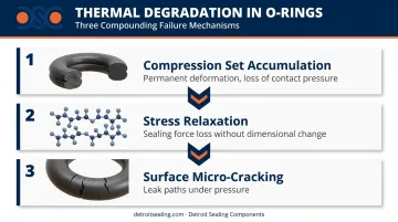
Over hundreds or thousands of cycles, three failure mechanisms compound:
- Compression set accumulation — the seal loses spring-back, reducing contact pressure against mating surfaces
- Stress relaxation — sealing force decreases even without dimensional change, as polymer chains reorganize under sustained load
- Surface micro-cracking — repeated strain cycling initiates cracks that become leak paths under pressure
None of these are visible to the naked eye until the seal has already failed in service.
The Cost of Skipping Testing
The consequences extend well beyond replacing a $2 O-ring:
- Pressurized fluid/gas systems: Unplanned downtime across automotive and industrial machinery carries significant costs — research on manufacturing downtime consistently places unplanned production stoppages among the most expensive operational risks
- Sensitive process environments: Semiconductor fabs, food processing, and healthcare applications cannot tolerate contamination from a failed seal
- Oil and gas: Pressure loss in downhole equipment risks well control and requires costly intervention
Material Variability Cannot Be Ignored
Those cost risks compound when the wrong elastomer is selected for the application's thermal profile. Different compounds respond to temperature cycling in distinct ways based on their coefficient of thermal expansion and glass transition temperature.
Nitrile (NBR) performs reliably at moderate temperatures but becomes brittle at sub-zero extremes. Silicone maintains low-temperature flexibility but gives up mechanical strength. FKM handles high-temperature oxidation well yet carries a higher glass transition point than silicone. Knowing a material's general reputation is a starting point — not a substitute for compound-specific testing against your actual thermal profile.
Key O-Ring Integrity Testing Methods for Thermal Cycling
No single test captures every failure mode. A defensible qualification program combines multiple methods, each targeting a specific degradation mechanism.
Compression Set Testing (ASTM D395)
Compression set testing measures the percentage of permanent deformation an O-ring retains after being held compressed at elevated temperature for a defined period. A high compression set value means the seal will not return to its original cross-section geometry after thermal exposure.
A seal that cannot return to shape cannot maintain contact pressure against mating surfaces — which is the fundamental failure compression set testing is designed to catch.
ASTM D395 Method B is the standard for O-ring applications. Common test parameters:
- Temperature: 70°C to 200°C depending on compound
- Duration: 22 hours or 70 hours at temperature
- Compression: 25% deflection (typical)
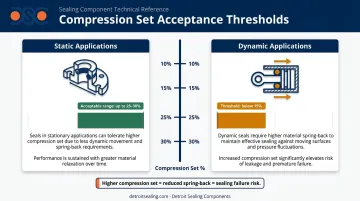
Acceptance thresholds: Static applications generally tolerate compression set values up to 25–30%. Dynamic applications require tighter control, often below 15%, since reduced spring-back directly impairs sealing under movement.
Thermal Shock and Thermal Cycling Chamber Testing
Thermal shock testing exposes O-ring samples to rapid alternating temperature extremes — for example, -40°C to +150°C — in a cycling chamber to simulate accelerated lifecycle conditions.
Key parameters that must be defined:
- Temperature range (minimum and maximum extremes)
- Ramp rate — gradual vs. shock transition between extremes
- Dwell time at each temperature extreme
- Cycle count — typically a multiplier of expected field cycles
Relevant frameworks include MIL-STD-810 Method 503 (temperature shock) and IEC 60068-2-14 (change of temperature testing). After cycling, samples are inspected for surface cracking, extrusion, or permanent deformation relative to baseline measurements.
Pressure Decay and Pressure Hold Testing
Pressure decay testing evaluates leak integrity by pressurizing a sealed assembly, holding pressure for a defined period after thermal conditioning, and measuring how much pressure is lost. Any decay beyond the specified threshold indicates the O-ring has lost sufficient sealing capability.
As a practical go/no-go test, it integrates directly into production validation workflows without requiring specialized tracer gas equipment. The tradeoff: pressure decay detects meaningful leaks, not micro-leaks below a few standard cubic centimeters per minute. For finer resolution, helium leak testing is the next step.
Helium Leak Testing
Helium leak testing is the most sensitive leak detection method available. Helium's small atomic radius allows it to escape through micro-leak paths that air or nitrogen cannot pass through at detectable rates.
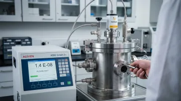
The assembly is pressurized with helium — or placed in a helium atmosphere — and a mass spectrometer detects tracer gas migration across the seal.
Standard in aerospace, semiconductor, and high-vacuum applications, helium leak testing can detect leak rates as low as 1×10⁻¹⁰ cc/sec — several orders of magnitude more sensitive than pressure decay testing. NASA and military aerospace standards use this method as the qualification benchmark for hermetic seals.
Low-Temperature Flexibility and Brittleness Point Testing (ASTM D2137 / TR-10)
Low-temperature testing assesses whether an O-ring compound will crack, fracture, or become too rigid to maintain sealing contact at the cold end of its thermal cycling range.
Two primary standards apply:
- ASTM D2137 — brittleness point testing, identifies the lowest temperature at which the material can absorb impact without fracturing
- TR-10 (Temperature Retraction) — measures the temperature at which a stretched sample retracts 10% of its elongation, indicating the onset of stiffness that compromises sealing
These tests are especially critical for seals that experience both high-heat exposure and sub-zero lows within the same operating cycle — a condition common in automotive underhood environments and outdoor industrial equipment.
Post-Cycling Dimensional Inspection and Hardness Testing
Before-and-after measurement of cross-section diameter, outer diameter, and Shore A durometer hardness quantifies what thermal cycling actually did to the material.
What the results indicate:
- Hardness increase → thermal oxidation or aging; the material is becoming brittle
- Hardness decrease → softening or chemical swelling
- Cross-section shrinkage → compression set progression; reduced contact force with mating surfaces
This is a relatively low-cost, quantitative complement to functional leak testing, and it provides a strong indicator of remaining service life. For these measurements to support engineering decisions, calibrated instrumentation and traceable test protocols are required. DSC's ISO 17025 accredited laboratory produces traceable hardness, compression set, and dimensional data — the documentation standard required for supplier qualification records.
How to Structure a Thermal Cycling Test Protocol for O-Rings
A test protocol must reflect the actual operating profile of the application, not a generic industry template. Each protocol covers:
- Temperature extremes and ramp rates
- Cycle count and dwell time
- Pressure conditions during cycling
- Pass/fail criteria for each test method
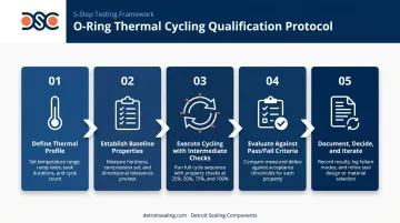
Step 1 – Define the Thermal Profile and Failure Modes of Concern
Identify:
- Actual minimum and maximum operating temperatures
- Expected thermal cycles over the component's full service life
- The most critical failure mode: leak, cracking, loss of sealing force, or dimensional instability
This determines which test methods to prioritize and how aggressive the test parameters need to be.
Step 2 – Establish Baseline Material Properties
Before any cycling begins, document:
- Durometer hardness (Shore A)
- Cross-section diameter and outer diameter
- Compression set at ambient temperature
- Elongation at break
These become the reference values against which post-cycling measurements are compared to quantify degradation.
Step 3 – Execute Cycling with Intermediate Checks
Run the selected cycling protocol, pausing at defined intervals (25%, 50%, 75%, 100% of target cycles) to conduct leak checks or dimensional sampling. Intermediate checks reveal when in the lifecycle degradation begins — which directly informs replacement interval recommendations rather than arbitrary scheduled maintenance.
Step 4 – Evaluate Against Pass/Fail Criteria
After cycling completes, run the full applicable test battery: compression set, dimensional inspection, hardness, and leak or helium leak testing. Compare results against pre-defined acceptance criteria.
Borderline results should trigger root cause analysis to determine whether the issue is material selection, groove geometry, or test parameter mismatch before any design or material changes are made.
Step 5 – Document, Decide, and Iterate
Test results must be formally documented with full traceability: lot number, compound designation, test conditions, equipment calibration records, and acceptance criteria. If the O-ring fails, the output is a material or design change recommendation. If it passes, the documentation becomes the qualification record. Without this traceability, the test data cannot support supplier qualification or regulatory review.
How DSC Can Help You Source and Validate Thermally Reliable O-Rings
Detroit Sealing Components (DSC) stocks compounds across the full elastomer spectrum, giving engineers a broad starting point for thermally optimized material selection without extended lead times on standard options:
- Nitrile (NBR) and Hydrogenated Nitrile (HNBR)
- Fluorocarbon (FKM/Viton) and Fluorosilicone (FVMQ)
- Silicone (VMQ) and EPDM
- Perfluoroelastomer (FFKM) for extreme-temperature applications
For applications where standard compounds fall short of thermal cycling requirements, DSC's ISO 17025 accredited laboratory supports custom material development and testing. The lab operates under traceable protocols, meaning the test data it generates can support engineering qualification decisions. When cycle-specific failure modes require a compound that isn't available off the shelf, DSC's technical team can develop and validate custom formulations with documented results.
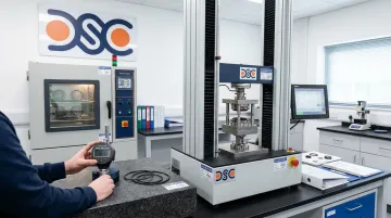
That material and lab capability extends to geometry and application fit as well:
- Custom O-ring sizes from 0.5mm ID up to 1600mm ID
- CAD and finite element analysis for groove design consultation
- Application engineering support for compound-application matching
This means engineers working through thermal cycling qualification get compound recommendations, test data, and geometry guidance from a single technical resource.
For application-specific compound recommendations or to discuss thermal cycling qualification requirements, DSC's technical team can be reached at 313-887-4695.
Conclusion
O-ring seal integrity under thermal cycling cannot be inferred from material datasheets or assumed based on compound reputation. It must be measured — through compression set testing, thermal shock protocols, pressure decay or helium leak testing, and dimensional inspection — across the actual temperature range and cycle count of the application.
Revisit your test protocol whenever operating conditions shift, suppliers update compound formulations, or field data shows degradation outpacing predictions. A protocol that matched last year's application may not cover today's.
DSC's ISO 17025 accredited lab supports both compound selection and validation testing under the same roof — which means the engineers helping you pick a material can also run the thermal cycling and leak tests that confirm it holds up. That shortens the path from initial specification to confident field deployment.
Frequently Asked Questions
What are the most important tests for O-ring seal integrity under thermal cycling?
Compression set testing (ASTM D395), thermal shock/cycling chamber tests, and pressure decay or helium leak testing form the core validation suite. Priority order depends on the primary failure risk — permanent deformation, surface cracking, or leakage — which varies by application and operating conditions.
Will an O-ring stop a leak?
A properly selected, sized, and installed O-ring will stop a leak under its rated conditions. Thermal cycling causes compression set and stress relaxation that reduce sealing force over time, so post-cycling leak testing is essential for any application with significant temperature variation.
What is the acceptable leakage rate for O-ring seals?
Acceptable leak rates depend entirely on the application and governing standard. For critical aerospace and semiconductor applications, helium leak testing can detect rates as low as 1×10⁻¹⁰ cc/sec. Less critical industrial applications may accept pressure decay thresholds measured in standard cubic centimeters per minute, with the threshold set by the system specification.
What is the life expectancy of an O-ring?
Service life ranges from under two years in aggressive thermal cycling to a decade or more in moderate, stable conditions — material choice, operating pressure, and cycle frequency all drive the variance. Periodic compression set and durometer hardness checks are the most practical tools for tracking seal condition in thermally demanding service.
Which O-ring materials perform best in thermal cycling applications?
FKM (Viton) and Silicone handle wide temperature ranges well. EPDM performs reliably in steam and outdoor thermal environments. FFKM offers the highest combined thermal and chemical resistance for extreme applications like semiconductor processing. Material selection must be validated through testing for your specific temperature extremes and cycle count.
How many thermal cycles should an O-ring be tested for before qualification?
Test cycle counts should mirror expected service life cycles with an acceleration factor of 1.5× to 2× applied. MIL-STD-810 and application-specific qualification requirements define minimum counts — the right number depends entirely on your use environment.