Introduction
A single underspecified component can bring down an entire hydraulic system. Pressure drops, fluid escapes, actuators respond sluggishly — and what started as a seal selection oversight becomes an unplanned shutdown on a 50-ton excavator or a flight control fault mid-mission.
Most engineers and maintenance professionals are comfortable specifying pumps and valves. Where systems fail more often is in the details : seal material selection, conductor sizing, and fluid compatibility. These are components that rarely get the same engineering attention but account for a disproportionate share of unplanned downtime.
Parker's Handbook of Hydraulic Filtration reports that over 75% of hydraulic and lube-oil system failures result directly from contamination — a statistic that implicates seals, filtration, and fluid management as much as pumps and valves.
What follows breaks down every major hydraulic component category: what each does, how common types compare, and a practical five-step selection framework. Whether you're specifying components for agriculture, oil and gas, aerospace, or automotive systems, the same principles apply.
Key Takeaways
- Every hydraulic system needs five core elements: reservoir, pump, control valves, actuators, and conductors
- Seals at every pressurized interface are non-negotiable — not optional add-ons
- Match pump type to pressure and flow demand; oversizing and undersizing both cause failures
- Select seal elastomer against the hydraulic fluid first, then check temperature range
- Parker ORD 5700 lists verified ranges: NBR to 121°C, FKM to 205°C, EPDM to 121°C
- A misspecified seal fails the system just as a wrong pump does — and gets caught far less often
How a Hydraulic System Works
Pascal's Law is the governing principle: pressure applied to an enclosed, incompressible fluid transmits equally in all directions. NASA's Glenn Research Center states this as P = F/A, which means pressure is constant through the fluid while output force scales with actuator area — a larger bore cylinder produces more force at the same pressure.
The hydraulic circuit follows a sequence:
- Power input — an electric motor or engine drives the pump
- Pressurization — the pump draws fluid from the reservoir and creates flow
- Control — directional, pressure, and flow control valves route and regulate that pressurized fluid
- Work output — actuators convert hydraulic energy into linear or rotary mechanical motion
- Return — fluid returns to the reservoir to cool, release air, and let contaminants settle before the cycle repeats
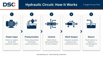
Each stage depends on the one before it. A mismatch anywhere — wrong pump displacement, incorrect valve rating, incompatible seal material (including seals and O-rings) — introduces heat, leaks, or premature failure. Selecting components means accounting for how each part behaves under the pressures, temperatures, and fluid types the whole system will see.
The Core Components of a Hydraulic System
Reservoir and Hydraulic Fluid
The reservoir does more than store fluid. It dissipates heat from returning fluid, allows entrained air bubbles to escape, and lets solid contaminants settle before fluid re-enters the pump. For open-circuit systems, Power & Motion recommends sizing at 3–5× pump flow per minute plus a 10% air cushion. Fire-resistant HFC/HFD fluids require 5–8× pump flow due to different thermal properties. Mobile equipment typically uses 1.5–2× because weight and space constrain tank size.
The three main hydraulic fluid families:
| Fluid Type | Common Use | Key Consideration |
|---|---|---|
| Mineral oil | Most industrial and mobile systems | Most cost-effective; widest seal compatibility |
| Synthetic (fire-resistant, waterless) | High-pressure, fire-risk environments | Verify seal compatibility — not all elastomers are suitable |
| Water-based (HFA, HFB, HFC) | Mining, steel mills, fire-hazard zones | Different reservoir sizing; specific seal requirements |
Fluid choice is not just a lubrication decision. It directly constrains which seal elastomers can be used throughout the entire system.
Hydraulic Pump
The pump is a power converter, not an energy source. It draws fluid from the reservoir and creates flow — pressure is a consequence of resistance to that flow downstream. The three common pump types each serve different operating conditions:
| Pump Type | Pressure Range | Flow Range | Best Application |
|---|---|---|---|
| Gear pump | Up to 280–310 bar (Parker PGP series) | Up to ~240 L/min | Constant-flow, lower-sensitivity systems |
| Vane pump | Up to 172 bar / 2,500 psi (Danfoss V10/V20) | 1–13 USgpm | Quiet industrial applications, moderate pressure |
| Piston pump | 280 bar nominal / 350 bar max (Bosch Rexroth A10VSO) | Variable displacement | High-pressure, variable-demand, efficiency-critical systems |
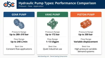
Gear pumps are simple and durable — the right choice when constant flow and lower pressure are acceptable. Vane pumps run quietly and suit many industrial settings. Piston pumps handle the heaviest duty cycles and offer variable displacement, but they require cleaner fluid and tighter maintenance.
Cavitation warning: if the pump inlet line is undersized, fluid viscosity is too high, or the reservoir layout creates suction restriction, absolute pressure at the inlet drops too low — bubbles form and collapse on the high-pressure side, eroding pump material and accelerating wear.
Inlet line sizing, strainer condition, and fluid viscosity all require review before specifying pump size.
Control Valves
Valves are the system's flow-routing and pressure-regulation layer. Three functional categories:
- Directional control valves — determine which path fluid takes, routing it to different actuators or reversing motion
- Pressure control valves — maintain system pressure within safe limits; relief valves divert excess fluid back to the reservoir
- Flow control valves — meter flow rate to regulate actuator speed
An incorrectly specified valve causes pressure surges, sluggish response, or uncontrolled motion. Parker's pilot-operated relief valves reach 420 bar / 6,000 psi at 400 L/min — illustrating why both pressure class and flow capacity must be matched to the circuit. Size for peak flow and transient pressure spikes, not steady-state conditions only.
For electro-hydraulic systems, proportional and servo valves respond to electronic signals, enabling programmable, feedback-controlled motion from a PLC or machine controller.
Actuators
Two types — cylinders and motors — serve fundamentally different motion requirements:
| Actuator | Motion Type | How Output Is Calculated | Typical Applications |
|---|---|---|---|
| Hydraulic cylinder | Linear (push/pull) | Pressure × piston area (pull force is lower due to rod reducing annular area on return stroke) | Lifting, pressing, clamping, positioning |
| Hydraulic motor | Rotary | Displacement × pressure differential × hydromechanical efficiency | Conveyors, winches, wheel drives, drill heads |
Actuator selection starts with load requirements and motion type. Mismatched bore size or motor displacement produces either inadequate force or uncontrolled speed — both are safety issues.
Conductors: Hoses, Tubes, and Fittings
Conductors carry pressurized fluid through the circuit. Per Parker Catalogue 4400/UK, hose burst pressure is generally 4× working pressure, and proof pressure testing runs at 2× working pressure for 30–60 seconds. Working pressure rating of the complete assembly is limited by its weakest component — fittings included.
When routing hoses, avoid:
- Sharp bends that restrict flow and stress the hose wall
- Abrasion points where contact with surfaces degrades the outer sheath
- Heat sources that accelerate fluid degradation and hose aging
Undersized or degraded hoses are a leading cause of hydraulic failures on field equipment. Surge pressure spikes can exceed rated working pressure — and often require instrumentation to catch them.
Sealing Components: Why They Make or Break Hydraulic Performance
Seals appear at every pressurized interface in a hydraulic system — cylinder rods, pistons, pump shafts, valve spools, accumulator ports, and threaded fittings. No other component category is this pervasive, which is why seal selection errors surface so visibly as leaks, pressure loss, and contamination.
Where Each Seal Type Lives
| Seal Type | Location | Primary Function |
|---|---|---|
| O-rings | Ports, connections, valve bodies | Static and low-speed dynamic sealing |
| Rod seals | Cylinder rod interface | Prevent fluid escaping along the rod |
| Piston seals | Cylinder bore | Maintain pressure differential across the piston |
| Wiper/scraper seals | Rod outer face | Exclude dirt and moisture on rod retraction |
| Backup rings | Behind O-rings under high pressure | Prevent O-ring extrusion through the gland gap |
Elastomer Selection: Fluid Compatibility First, Temperature Second
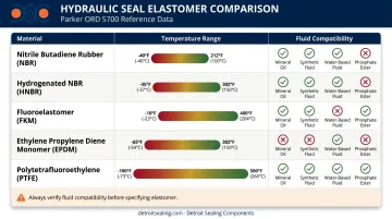
Selecting an elastomer without checking fluid compatibility is the most common seal specification error. Different hydraulic fluids attack different rubber compounds, causing swelling, shrinkage, or cracking that leads to leaks and blowout under pressure.
| Material | Temperature Range (Parker ORD 5700) | Fluid Compatibility |
|---|---|---|
| NBR / Buna-N | −34°C to 121°C | Mineral oil, HFA/HFB/HFC; not for phosphate esters |
| HNBR | −32°C to 149°C | Mineral oil at higher temps; improved abrasion resistance |
| FKM / Viton | −26°C to 205°C | Mineral oil, synthetic HFD fluids; check before using with water-based fluids |
| EPDM | −57°C to 121°C | Phosphate ester, glycol systems; not compatible with petroleum oils |
| PTFE | Below −73°C to 204°C+ | Broad chemical compatibility; used as backup rings or in demanding conditions |
The Consequences of Getting It Wrong
- Incorrect material → seal swells, shrinks, or hardens; leaks develop quickly
- Wrong geometry or sizing → extrusion through the gland gap at pressure
- Fluid incompatibility → accelerated degradation, system contamination, environmental spill
DSC supplies hydraulic sealing solutions across all five elastomer families. The product range covers:
- O-rings in AS568, metric, and JIS sizes
- Wiper seals (UA2, UA4) and rod/piston seals (UF1, UF2, UF4, UH1, UH2, UC6)
- Backup rings in 90-durometer NBR and FKM for the complete AS568 series, designed to raise O-ring pressure capability without added gland complexity
For non-standard sizes or custom geometries, DSC applies CAD and finite element analysis to simulate seal behavior under real operating conditions before cutting tooling. DSC's ISO 17025 accredited lab also supports material compatibility verification between a customer's specific hydraulic fluid and a proposed elastomer compound — particularly valuable when switching fluid types or operating near the edge of a material's temperature or chemical resistance window.
How to Select the Right Hydraulic Components
Work through these five steps in order. Selecting a pump before confirming fluid type, or specifying seals before setting operating pressure, creates mismatches that are expensive to correct in the field.
Step 1 — Define System Requirements
Before selecting any component, establish:
- Operating pressure (psi / bar) — steady-state and peak
- Flow rate (GPM / LPM)
- Hydraulic fluid type and ISO viscosity grade
- Temperature range — ambient and operating fluid temperature
- Duty cycle — continuous, intermittent, or shock-load
- Environmental exposures — UV, abrasion, washdown, chemical splash
These parameters form the selection filter for every downstream decision.
Step 2 — Match Pump Type to Pressure and Flow
- Gear pump: appropriate for constant-flow, lower-pressure applications where simplicity and contamination tolerance matter
- Vane pump: suits moderate-pressure industrial systems where noise is a concern
- Piston pump: required for high pressure, variable displacement, or high-efficiency systems
Oversizing wastes energy and generates heat. Undersizing causes cavitation. Both shorten system life.
Step 3 — Select Valves Based on Control Requirements
Specify each of the following before committing to a valve:
- Pressure class and flow capacity (Cv rating)
- Actuation method: manual, solenoid, or proportional/servo for precision control
- Response time requirements
- For electro-hydraulic integration: valve bandwidth and hysteresis if the application requires tight position or force control
Step 4 — Choose Actuators for Load, Motion, and Stroke
- Confirm bore diameter against force requirements using Force = Pressure × Effective Area
- Verify operating pressure matches actuator ratings
- For rotary applications, match motor displacement to required torque and speed, accounting for hydromechanical efficiency losses
Step 5 — Validate Seals, Hoses, and Fittings
This step is non-negotiable and the most commonly shortcut:
- Cross-reference seal elastomer against the hydraulic fluid using a chemical compatibility chart
- Verify hose working pressure exceeds maximum system pressure including surge spikes, with a 4:1 burst margin
- Confirm fitting thread type and size matches all mating connections
- Check seal temperature rating against both ambient cold-start and peak operating temperature
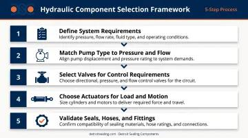
An improperly specified seal or hose causes the same failure as a wrong pump. The difference is that seal and hose specifications receive a fraction of the engineering scrutiny.
Hydraulic Components Across Key Industries
Agriculture and Construction
Mobile equipment demands heavy-duty cylinders rated for shock loads, gear or piston pumps that tolerate contaminated environments, and seals with strong abrasion resistance across wide temperature swings. NBR and HNBR are the dominant elastomers here — HNBR particularly where daily temperature cycles from cold morning starts to sustained operating heat would degrade standard NBR prematurely.
Space and weight constraints mean mobile reservoirs are typically sized at 1.5–2× pump flow, which puts a higher burden on filtration, breathers, and exclusion seals to keep contamination under control.
Oil & Gas and Industrial Manufacturing
Aggressive or fire-resistant hydraulic fluids are common in these sectors. Key component requirements include:
- FKM (Viton) or HNBR seals to handle aggressive fluid chemistries
- Precision piston pumps and pilot-operated relief valves for high-pressure circuits
- Fine filtration to protect tight-tolerance servo valves and pump pistons from particle damage
Contamination control is non-negotiable. Particles invisible to the naked eye damage components that cost thousands of dollars to replace.
Aerospace and Automotive
Weight, dimensional precision, and cleanliness dominate every component decision. Synthetic hydraulic fluids — phosphate ester (Skydrol) or polyol ester (MIL-PRF-83282) — are standard, and each drives a specific seal material requirement. EPDM is correct for phosphate ester systems; FKM suits hydrocarbon synthetic fluids. Mixing seal materials with incompatible fluids does not create a compatibility risk — it creates certain seal failure.
Off-the-shelf seal profiles often don't achieve the leak-free performance these applications require. Custom-molded geometries, verified with finite element analysis (FEA) and bench testing, are frequently necessary when tolerances are tight and fluid cleanliness requirements are strict.
Frequently Asked Questions
What are the main components of a hydraulic system?
The five core elements are the reservoir, hydraulic pump, control valves, actuators (cylinders or motors), and conductors (hoses, tubes, and fittings). Sealing components at every pressurized interface — rod seals, piston seals, O-rings, wipers — are equally essential for maintaining system integrity and preventing fluid loss.
What are the components of a hydraulic power unit?
A hydraulic power unit (HPU) is a self-contained package combining a reservoir, electric motor or engine, hydraulic pump, pressure relief valve, and filtration into one modular assembly.
What is an electro-hydraulic system?
An electro-hydraulic system integrates electronic controls — sensors, a controller, and electrically actuated valves such as solenoid or proportional/servo valves — with a conventional hydraulic circuit to enable programmable, closed-loop control of force and motion.
What is the difference between hydraulic and electro-hydraulic?
A conventional hydraulic system relies on mechanical or manual valve actuation. An electro-hydraulic system replaces that with electronic signals, allowing integration with PLCs and machine controllers for automated, repeatable operation.
What are the components of an electro-hydraulic system?
Beyond standard hydraulics, electro-hydraulic systems add an electronic control unit (ECU or PLC), position or pressure sensors, solenoid or proportional/servo valves, and signal conditioning electronics.