Introduction
In EV modules, stationary storage packs, and high-voltage industrial assemblies, a gasket's thermal resistance directly controls how quickly heat moves between cells, modules, and enclosures. A poor selection doesn't just compromise sealing — it can turn a localized thermal event into a system-level failure.
The problem is that thermal resistance is frequently misunderstood. Engineers often treat a gasket's continuous service temperature as its thermal protection limit — these are not the same thing. A silicone gasket rated for 200°C continuous service is not a thermal runaway firewall.
Thermal resistance is a calculable, measurable parameter: R = t/k. It changes under compression, over time, and under thermal cycling.
This guide covers how thermal resistance works in battery gasket engineering, which materials deliver which performance ranges, and how to specify correctly so that in-service behavior matches design intent.
Key Takeaways
- Thermal resistance is calculated as R = t/k (thickness ÷ thermal conductivity), not read from a temperature rating
- Silicone (~0.2 W/m·K) suits moderate thermal environments; aerogel composites (<0.045 W/m·K) and mica handle high-temperature or thermal runaway scenarios
- Compression reduces gasket thickness and lowers in-service R-value immediately; compression set degrades it permanently over time
- Always verify your calculated R-value under actual compression and temperature conditions before finalizing a specification
- Composite stackups (sealing layer plus thermal barrier layer) are now standard practice in high-energy-density battery pack design
What Thermal Resistance Represents in Battery Gaskets
Thermal resistance in a flat gasket is defined by a straightforward relationship: R = t/k, where t is thickness in meters and k is thermal conductivity in W/m·K. The result, expressed in m²·K/W, tells you how strongly the gasket opposes heat flow per unit area.
R-value is not a temperature rating or a flame retardancy classification. A gasket can carry a UL 94 V-0 flame rating and still conduct too much heat for its application — and a high R-value offers no protection against mechanical failure under sustained compression. These are distinct properties that require separate specification.
How Thermal Resistance Functions in a Battery System
In a battery pack, the gasket sits at the interface between thermally stressed components. Its R-value acts as a rate limiter on heat transfer, controlling how quickly thermal energy moves from a hot cell to adjacent cells or structural components. That rate-limiting function feeds directly into thermal propagation risk assessment.
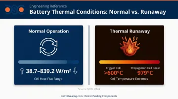
Research from NREL's 2024 thermal runaway propagation study reported trigger-cell temperatures exceeding 600°C during active runaway events, with propagation-cell peaks reaching 979°C. Under normal charge/discharge conditions, a 2026 Applied Thermal Engineering study measured cell heat flux ranging from 38.7 W/m² at moderate conditions to 839.2 W/m² at low temperature and high C-rate.
Those two scenarios — normal operation and thermal runaway — represent fundamentally different thermal boundary conditions. Specifying a gasket material against one condition while ignoring the other is where most specification failures originate.
Design Parameter vs. Operating Variable
That failure risk points to a broader design challenge: thermal resistance is both a fixed design input and a moving target in service. Engineers set a target R-value based on heat flux analysis at the design stage — but that value shifts as conditions change. Three factors drive the drift:
- Compression under clamping load — reduces effective thickness, lowering R-value
- Thermal cycling fatigue — degrades material structure over time, altering conductivity
- Elevated-temperature material degradation — permanently changes the gasket's thermal properties
Understanding that dynamic is as important as reading the initial datasheet.
Thermal Resistance Ranges and Material Selection
The R-value a gasket delivers in service depends on two interacting parameters: the intrinsic thermal conductivity of the base material and the installed thickness within the pack's spatial envelope. The table below addresses conductivity by material type — thickness enters the equation during stackup design, covered in the next section.
Standard Performance Ranges by Material Type
| Material | Typical k-value (W/m·K) | Continuous Temp. Limit | Approx. R at 2 mm (m²·K/W) | Primary Battery Role |
|---|---|---|---|---|
| Silicone rubber | ~0.20 | 150–200°C (>10,000 h) | ~0.010 | Module sealing, moderate thermal environments |
| EPDM | ~0.25 | 150–155°C | ~0.008 | Enclosure sealing, environmental ingress protection |
| Phlogopite mica | 0.20–0.25 | Up to 1000°C | ~0.008–0.010 | Thermal firewall layer in high-voltage assemblies |
| Muscovite mica | 0.50–7.0 | ~600°C | Varies widely | Electrical/thermal barrier — grade-specific k required |
| Aerogel composite | <0.045 (ASTM C518) | Designed for runaway events | >0.044 | Low-conductivity barrier layer in high-risk stackups |
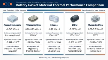
For most battery module sealing applications, silicone rubber (~0.20 W/m·K) is the default elastomeric choice. Shin-Etsu property data shows continuous service up to 200°C for more than 10,000 hours, with selected grades meeting UL 94 V-0. Good conformability and chemical resistance make it well-suited where extreme thermal events are not the primary design concern.
EPDM (~0.25 W/m·K) has a lower continuous service ceiling — typically 150–155°C — and fits enclosure-level sealing and environmental protection better than module-level thermal management. Compression set behavior is a documented concern: Marco Rubber test data shows EPDM compression set reaching 83.3% after 168 hours at 288°C, representing severe permanent thickness loss that directly reduces installed R-value over time.
Mica composites split into two grades with very different capabilities. Phlogopite maintains structural integrity up to 1000°C, making it the appropriate choice for thermal firewall duty in runaway protection zones. Muscovite is rated to approximately 600°C but carries a wide k-value range (0.5–7.0 W/m·K depending on grade and orientation) — confirm the specific grade's k-value before calculating any R target.
Aerogel composites deliver the lowest thermal conductivity available in a flexible barrier format. 3M's Thermal Runaway Barrier 600/700 series reports k < 0.045 W/m·K by ASTM C518 at 25°C, positioned specifically for runaway propagation reduction. Aspen's PyroThin targets cell-to-cell, module, and pack-level mitigation. The trade-off is mechanical: aerogel sheets are not elastomeric, so compression must be controlled carefully to preserve installed thickness and the R-value that depends on it.
Composite Stackups: Resolving the Sealing vs. Thermal Resistance Trade-Off
Materials offering the lowest thermal conductivity — mica, aerogel — typically provide poor conformability and sealing performance on their own. Elastomers seal well but have limited thermal resistance at extreme temperatures.
The engineering solution is a layered stackup that assigns each function to the most capable material:
- Sealing layer: Silicone or EPDM, conforming to surface irregularities under compression
- Thermal barrier layer: Aerogel or mica composite, providing the target R-value and flame resistance
- Dielectric layer: Where electrical isolation is required, an additional layer addresses that independently
This multi-material approach is now the standard in high-energy-density battery pack design. A single interface must seal against ingress, provide measurable thermal resistance, and survive abuse conditions — no single material does all three well, so the stackup does.
Key Technical Properties That Govern Thermal Resistance Performance
Thermal Conductivity vs. Thermal Resistance
These terms describe related but distinct properties. Thermal conductivity (k) is an intrinsic material constant — it describes how the material itself transfers heat, regardless of geometry. Thermal resistance (R = t/k) is a system-level property that depends on both the material and the thickness installed.
Specifying a gasket by temperature rating rather than k-value creates a real gap: two gaskets with identical temperature ratings but different k-values will deliver significantly different R-values at the same thickness. When that difference goes unaccounted for, thermal protection assumptions fail in the field.
Compression Set: The Long-Term Threat to R-Value
Compression set is the permanent thickness reduction a gasket sustains after prolonged compression under load and temperature. Because R = t/k, any permanent reduction in thickness directly reduces thermal resistance — even if the gasket still provides adequate sealing force.
Key data points from published testing:
- Silicone: Compression set typically 10–20% after elevated-temperature 22-hour tests (Shin-Etsu data). Relatively stable across -60°C to +250°C.
- EPDM: 18% compression set at 125°C for 70 hours; 83.3% after 168 hours at 288°C (Marco Rubber E1079 test data). Unsuitable for sustained high-temperature environments.
- Mica/aerogel composites: Not evaluated by ASTM D395 (a rubber-specific method). Specify retained thickness after compression cycling and crush resistance as the relevant mechanical criteria.
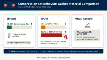
For an 8–15 year EV battery pack service life, initial R-values measured on uncompressed room-temperature samples are not enough — thermal resistance must be verified after compression set aging and thermal cycling to reflect real service conditions.
How Thermal Resistance Is Specified, Measured, and Validated
Specification and Documentation
Material datasheets report thermal conductivity (k, W/m·K) rather than thermal resistance directly. The engineer's job is to calculate R = t/k for the specific installed thickness, then compare that against the system-level thermal requirement from heat flux analysis.
Relevant standards for battery gasket specification:
- ASTM C518 — Steady-state thermal transmission through flat slabs using a heat flow meter apparatus. Appropriate for thicker barrier sheets.
- ASTM E1530 — Thermal resistance of thin specimens by guarded heat flow meter. Applicable to thin gaskets and thermal interface pads.
- ASTM D395 — Compression set testing for rubber compounds. Critical for assessing long-term thickness retention.
- UL 94 V-0 — Minimum flame retardancy benchmark for battery applications. A flame classification, not a thermal resistance requirement — specify both separately.
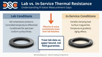
One critical distinction: rated thermal conductivity values (tested under ASTM-controlled conditions) are baselines, not guaranteed in-service values. They assume controlled compression, temperature, and surface finish. Field conditions consistently produce lower effective R-values.
Measurement Methods and the Lab-vs-Field Gap
The two primary lab measurement methods (guarded hot plate and heat flow meter apparatus) both require controlled contact pressure, temperature differentials, and sample conditioning. Results are sensitive to all three parameters, which is why test reports should always state the compression pressure, temperature, specimen thickness, and conditioning used. Without those fields, R-values from different suppliers are not directly comparable.
In-service compression, surface irregularities, and temperature gradients produce thermal resistance values that consistently fall below lab-tested figures. The discrepancy is systematic, not marginal — treat lab data as an upper bound for design purposes, not a field performance guarantee.
When datasheet values aren't sufficient for design sign-off, application-specific validation closes that gap. DSC's ISO 17025 accredited laboratory supports custom compound characterization and thermal resistance testing under application-specific compression loads and temperature conditions — useful when developing custom formulations for battery-specific thermal requirements.
Risks of Misspecification
Treating Service Temperature as Thermal Runaway Protection
The most consequential misread in battery gasket selection is assuming that a gasket rated for 200°C continuous service can function as a thermal barrier during a thermal runaway event. Thermal runaway is not a continuous operating condition — it generates localized temperatures of 600–1000°C over a short, intense duration.
An elastomeric gasket will not survive that exposure. It may retain its seal function up to its service temperature limit, but it provides no meaningful thermal resistance once that threshold is crossed. These are separate design cases requiring separate specification criteria and, typically, separate material layers.
Compression-Set-Induced Drift: The Invisible Failure Mode
A gasket that meets its thermal specification at assembly may have significantly degraded R-value after years of thermal cycling. The mechanism is gradual: each heat-cool cycle causes incremental compression set, which reduces gasket thickness and, with it, effective R-value — accumulating invisibly over the pack's service life.
This failure mode is particularly dangerous because it doesn't surface during routine inspection. The gasket may still look intact, maintain adequate sealing force, and pass visual quality checks — while delivering significantly less thermal resistance than the propagation model assumed.
Single-Material Specification in High-Risk Zones
Applying a single gasket material in a zone that requires layered thermal protection meets sealing requirements while leaving thermal runaway containment inadequate. The practical consequence: a cell thermal event that should be contained at the module boundary propagates instead, because the thermal resistance separating adjacent cells is insufficient.
Well-engineered battery thermal protection designs use multi-material stackups that assign distinct functions across layers:
- Sealing layer — maintains compression seal and electrolyte resistance
- Thermal resistance layer — limits heat transfer between adjacent cells
- Dielectric layer — provides electrical isolation under fault conditions
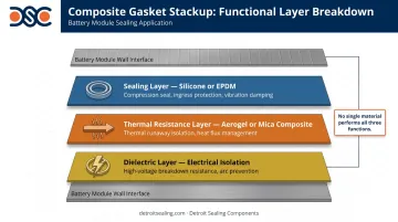
Specifying a single elastomeric gasket where a composite barrier is required creates a genuine performance gap. In applications subject to UL 9540A system-level thermal runaway fire propagation evaluation, that gap also carries direct compliance and warranty exposure.
Conclusion
Thermal resistance is not a label — it's a calculated, measurable, and change-over-time parameter that must be actively managed through material selection, thickness specification, compression load control, and aging allowance. Selecting a battery gasket by temperature rating alone leaves the actual thermal protection performance unquantified.
Engineering judgment must bridge the gap between published datasheet values and what actually happens in a compressed, aged, thermally cycled assembly. That means:
- Calculating R = t/k from verified k-values at installed thickness
- Specifying compression set limits appropriate to the pack's service life
- Designing with enough thermal resistance margin that a degraded gasket at end-of-life still meets the system's heat flux requirements
When a single material cannot satisfy all requirements simultaneously — sealing, thermal resistance, flame resistance, dielectric isolation — a composite stackup is the correct specification, not an over-engineering choice. Define each functional requirement before selecting any individual layer, and the right construction follows from the constraints.
Frequently Asked Questions
What gaskets can withstand heat?
Silicone and EPDM handle moderate continuous heat up to approximately 150–200°C, making them suitable for typical battery module and enclosure sealing. For extreme or transient high-temperature environments (including thermal runaway protection zones), mica composites — phlogopite grade rated up to 1000°C — and aerogel-based barrier sheets are the appropriate material categories.
What is the thermal conductivity of a gasket?
Thermal conductivity (k, W/m·K) is the material-level property measuring heat transfer rate. Representative values: silicone ~0.20 W/m·K, EPDM ~0.25 W/m·K, phlogopite mica 0.20–0.25 W/m·K, aerogel composites <0.045 W/m·K. Lower k-values indicate better thermal insulation — aerogel composites offer the best insulating performance in a flexible barrier format.
Can AGM batteries experience thermal runaway?
AGM (absorbent glass mat) lead-acid batteries can experience thermal runaway under overcharge or sustained high-rate discharge conditions, though the temperature dynamics differ from lithium-ion chemistry. Gasket thermal resistance selection for AGM applications should account for peak temperatures generated during a thermal event, not just normal operating ranges.
What is the difference between thermal resistance and thermal conductivity in a battery gasket?
Thermal conductivity (k) is the intrinsic material constant describing how a material transfers heat, independent of geometry. Thermal resistance (R = t/k) is the system-level property determined by both material and installed thickness, giving engineers a calculable, directly comparable parameter for gasket selection.
What material is best for EV battery module gaskets?
No single material covers all requirements. Silicone offers the best balance of sealing conformability, moderate thermal resistance, and chemical resistance for conventional module applications. Where thermal runaway containment is the primary requirement, composite stackups combining a silicone sealing layer with a mica or aerogel thermal barrier are increasingly the engineering standard for high-energy-density packs.
How does compression affect gasket thermal resistance over time?
Compression reduces gasket thickness at assembly, lowering the in-service R-value immediately. Over the pack's service life, thermal cycling causes permanent compression set, further degrading thermal resistance. Specify materials with low compression set rates and design in a thermal resistance margin that accounts for end-of-life thickness loss, not just initial values.