Introduction
A single incorrect O-ring dimension, wrong material choice, or tolerance oversight can trigger system failures, hazardous leaks, and emergency shutdowns — problems that cascade into thousands of dollars in downtime. Unplanned downtime costs global industries approximately $1.4 trillion annually, with seal failure as a significant contributor.
The data behind these failures is instructive: analysis of over 500 seal failures shows that nearly 50% stem from physical or mechanical issues — specifically assembly faults and incorrect clearance design — rather than material degradation alone.
Getting the specification right the first time is essential to operational reliability and cost control. This guide walks through each critical parameter — inside diameter, outside diameter, cross-section, material selection, and tolerances — so you can specify custom O-rings with confidence.
Key Takeaways
- Measure ID, OD, and cross-section (CS) precisely — errors in any dimension lead to seal failures and costly downtime
- Standard sizing systems (AS568, ISO 3601) ensure availability and cost-effectiveness when properly applied
- Match material to operating temperature, chemical exposure, and whether the seal is static or dynamic
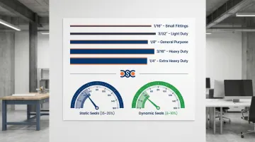
- Target 15–25% compression for static seals, 8–16% for dynamic, with 75–85% groove fill to prevent extrusion
- ISO 17025 accredited testing confirms material compatibility and supports custom compound development for demanding applications
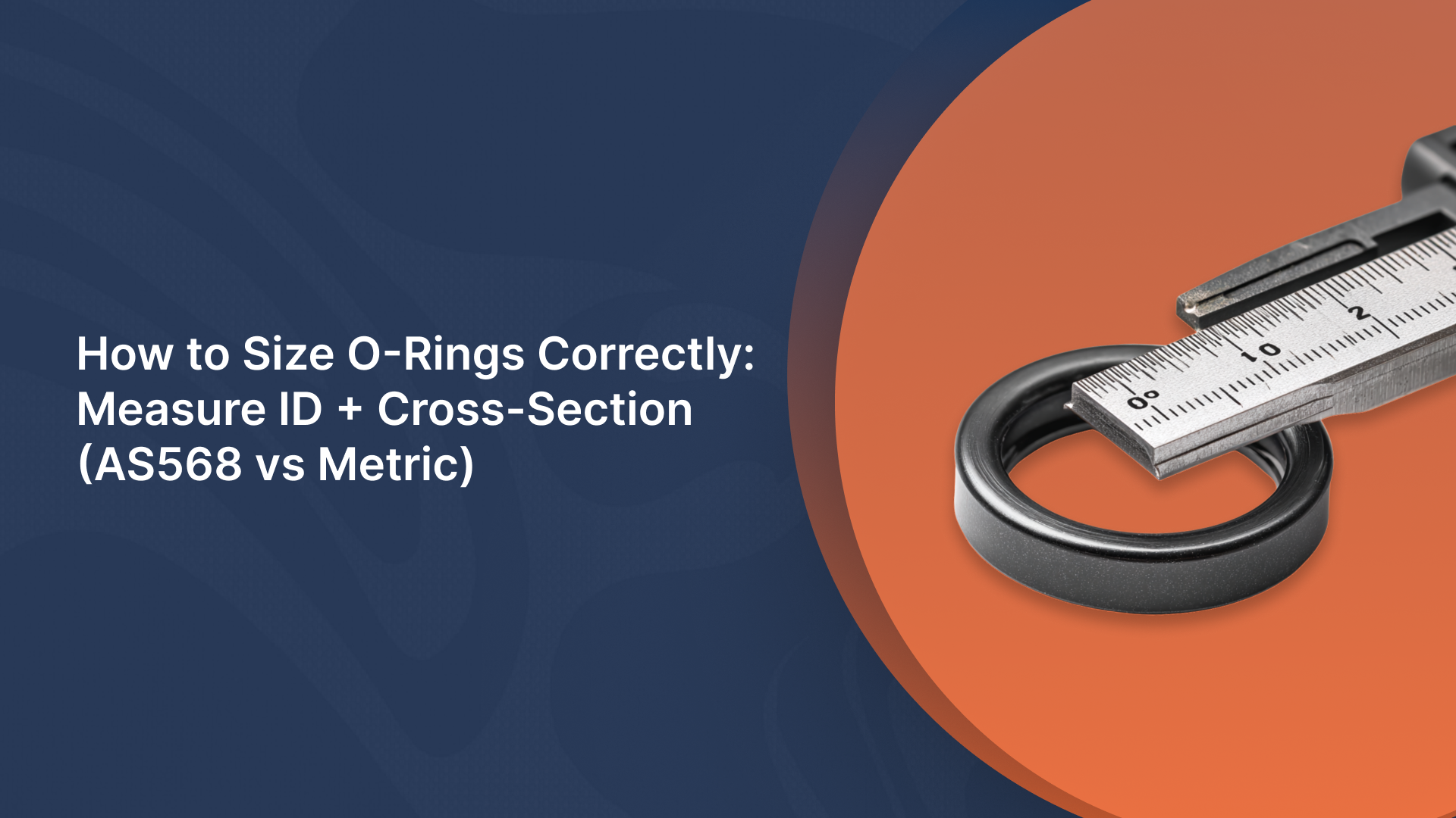
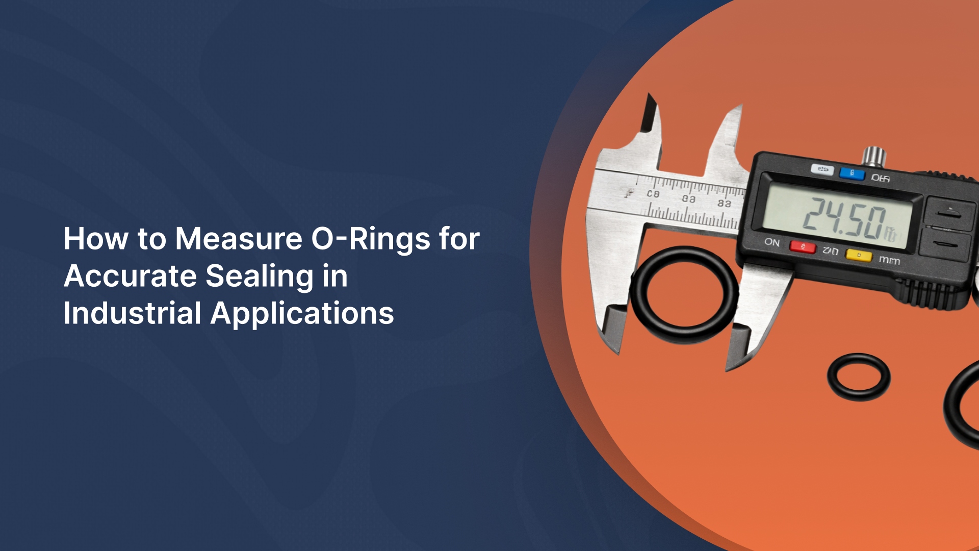
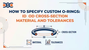
Understanding O-Ring Dimensions: ID, OD, and Cross-Section
These three measurements form the foundation of any O-ring specification. Understanding how each dimension affects seal performance prevents costly specification errors that lead to leaks, installation damage, or premature failure.
Inner Diameter (ID)
ID is the measurement across the inner opening of the O-ring in its free (unstressed) state. This dimension relates directly to the shaft or bore diameter the O-ring will seal against. For piston seals, size the ID to the shaft diameter; for rod seals, size it to the bore.
What happens when ID is wrong:
- Undersized ID causes installation damage, excessive stress, and premature cracking
- Oversized ID results in seal failure, leaks, and potential extrusion under pressure
Installation stretch limits: For piston seals, the ID should be stretched between 2% and 5% for dynamic applications and 2% and 8% for static applications. Exceeding 5% in dynamic applications reduces seal life significantly.
Outer Diameter (OD)
OD is the total width measured from one outer edge to the opposite outer edge. This dimension determines groove fit and must provide proper compression without overfilling the groove.
Key relationship: OD = ID + (2 × CS)
You calculate OD from ID and CS — not measure it directly. This matters for groove design: an incorrect OD calculation leads to overfill conditions and extrusion under pressure.
Rod seal installation limits:
- OD must not exceed housing OD by more than 5% when ID < 250mm
- OD must not exceed housing OD by more than 3% when ID > 250mm
- Exceeding these limits causes buckling during installation
Cross-Section (CS)
CS is the thickness of the O-ring material—the diameter of the circular cross-section. This dimension determines compression percentage and seal effectiveness. CS must be larger than groove depth to achieve proper compression and create an effective seal.
Common standard cross-sections and typical applications:
- 1/16" (0.070"): Compact static seals, light-duty dynamic applications
- 3/32" (0.103"): General static/dynamic, standard hydraulic fittings
- 1/8" (0.139"): General industrial, larger static flanges
- 3/16" (0.210"): Heavy-duty static, large diameter cylinders
- 1/4" (0.275"): Large heavy-duty static, reactor vessels
Target 15–25% compression for static seals and 8–16% for dynamic seals. Both ranges depend on CS exceeding groove depth by the right margin — too little compression causes leaks, too much accelerates wear.
O-Ring Size Standards and Tolerances
Choosing the right sizing standard determines whether an O-ring is readily available off the shelf or requires custom tooling. Tolerance class affects manufacturing cost, lead time, and how consistently the seal performs under load — so it's worth understanding both before you specify.
AS568 Standard (Aerospace Standard)
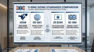
AS568 is the most widely used O-ring sizing standard in North America, published by SAE International. The current revision is AS568F (2020).
Each size is designated by a dash number (e.g., -010, -214) corresponding to specific ID and cross-section combinations. The system covers 369 standard sizes with IDs ranging from 0.029" to 25.940".
Six series groups are organized by cross-section diameter:
- -0xx Series: 0.070" CS
- -1xx Series: 0.103" CS
- -2xx Series: 0.139" CS
- -3xx Series: 0.210" CS
- -4xx Series: 0.275" CS
- -9xx Series: Boss seals for tube fittings (0.064" to 0.116" CS)
ISO 3601 and Metric Standards
ISO 3601 defines metric O-ring sizes used internationally. ISO 3601-1 (2012) covers inside diameters, cross-sections, tolerances, and designation codes.
Two tolerance classes apply under ISO 3601-1:
- Class A (Aerospace): Corresponds to AS568 sizes with tighter tolerances for critical aerospace and industrial applications
- Class B (General Purpose): Covers broader metric sizes with slightly wider tolerances for general fluid power applications
Several regional standards still appear in legacy and international specifications:
- DIN 3771 (Germany): Historically significant; officially withdrawn but still referenced in legacy specifications
- JIS B 2401 (Japan): Organizes sizes by application: P (Dynamic), G (Static), S (Special), and V (Vacuum)
- BS 1806 (UK): Lists imperial sizes similar to AS568; largely superseded by BS ISO 3601
Because AS568 and ISO 3601 share similar cross-section dimensions across many sizes, cross-standard substitution is often feasible — useful when sourcing internationally or qualifying alternate suppliers.
Tolerance Classes and When to Use Them
Standard tolerance classes per ISO 3601-1 Class B suffice for most static industrial applications. Tighter tolerances (ISO 3601-1 Class A) are necessary for:
- Aerospace applications requiring critical dimensional control
- High-precision dynamic sealing where friction control is essential
- Automated assembly where slight variations cause jamming
- High-pressure applications demanding consistent compression
Tighter tolerances require specialized molds calibrated for exact material shrinkage, plus more rigorous inspection per ISO 3601-3 Grade S. Expect higher unit costs from increased rejection rates and inspection labor, and longer lead times when custom tooling is needed for a specific compound's shrink rate.
Stretch and Compression Limits
Staying within installation limits prevents stress cracking, seal distortion, and early failure in service.
Acceptable stretch limits:
- Static applications: Up to 8% (2-8% recommended)
- Piston seals in dynamic applications: Up to 5% (2-5% recommended)
Acceptable compression limits:
- Static applications and rod seals: Up to 3-5% depending on O-ring size
- Larger O-rings (ID > 250mm): Maximum 3% compression
- Smaller O-rings (ID < 250mm): Maximum 5% compression
Material Selection for Custom O-Rings
Material choice is as critical as dimensional accuracy. The wrong material leads to rapid degradation, swelling, hardening, or chemical attack—often within hours of installation in aggressive environments.
Operating Temperature Range
Temperature extremes affect elastomer performance predictably: low temperatures cause hardening and brittleness, while high temperatures cause softening, degradation, and compression set.
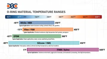
Common materials by temperature range:
| Material | Temperature Range | Typical Applications |
|---|---|---|
| Nitrile (NBR) | -40°F to 250°F (-40°C to 121°C) | Petroleum oils, hydraulic fluids |
| Viton (FKM) | -15°F to 400°F (-26°C to 205°C) | Aggressive chemicals, high-temp fluids |
| EPDM | -65°F to 300°F (-54°C to 149°C) | Water, steam, brake fluids |
| Silicone (VMQ) | -80°F to 450°F (-62°C to 232°C) | Wide temperature range, food contact |
| FFKM (Kalrez) | +5°F to 608°F (-15°C to 320°C) | Extreme chemical and temperature environments |
Document the minimum and maximum operating temperatures your application will experience, including startup conditions and thermal cycling. Select a material whose temperature range covers your requirements with a safety margin of at least 20°F on each end.
Chemical Compatibility
Chemical exposure is the primary cause of O-ring material failure. Incompatible materials swell, crack, harden, or dissolve when exposed to certain fluids or gases.
Common chemical environments and compatible materials:
- Petroleum oils/fuels: Nitrile (NBR) is standard; Hydrogenated Nitrile (HNBR) offers improved temperature and abrasion resistance
- Aggressive chemicals/acids: Viton (FKM) is standard; FFKM (Kalrez) required for extreme resistance where FKM fails (amines, strong bases)
- Water/steam: EPDM is excellent for hot water and steam up to 300°F but incompatible with petroleum oils
- Food contact: FDA-grade Silicone (VMQ) and EPDM are widely used for food processing equipment
Cross-reference your specific fluids and gases against manufacturer compatibility databases (Parker, Trelleborg). For complex or unknown chemical exposure, DSC's ISO 17025 accredited lab and ISO 9001:2015 certified quality system can test candidate materials against your actual process fluids before you commit to production quantities.
Hardness (Durometer) Selection
Durometer measures material hardness, typically ranging from 50 to 90 Shore A for O-rings. Hardness selection affects both sealing capability and extrusion resistance.
Selection guidance:
- 50-60 Shore A (soft): Seals well at low pressures and conforms to rough surfaces; extrudes under high pressure
- 70-80 Shore A (medium): Balances sealing and extrusion resistance for most general industrial applications
- 80-90 Shore A (hard): Resists extrusion at high pressures but requires higher seating forces and may not conform to surface irregularities
Pressure considerations: At 100 bar pressure with a 0.4mm clearance gap, a 70 Shore A O-ring will extrude, whereas a 90 Shore A O-ring (or use of a backup ring) is necessary to prevent failure.
Static vs. Dynamic Applications
Static seals involve no relative motion between sealing surfaces. They tolerate higher compression (15-25%) and softer compounds that conform to surface irregularities.
Dynamic seals involve reciprocating or rotary motion, which changes the requirements significantly. To reduce friction and extend service life, dynamic applications require:
- Compression held to 8-16% to minimize friction and wear
- Low-friction compounds such as PTFE-filled Nitrile or specific Viton grades
- Higher abrasion resistance than static equivalents
- Tighter dimensional tolerances to maintain consistent compression during motion
FDA, NSF, and Industry-Specific Requirements
Common certifications by industry:
| Certification | Industry | What It Covers |
|---|---|---|
| FDA 21 CFR 177.2600 | Food & Beverage | Rubber articles for repeated food contact |
| NSF/ANSI 61 | Potable Water | Prevents contaminant leaching into drinking water |
| USP Class VI | Medical/Pharma | Most stringent biocompatibility standard |
| WRAS / W270 / ACS | International Water | Regional drinking water standards (UK, EU, France) |
When standard certified materials don't meet your application's requirements, custom compounds can be formulated and validated against the relevant standard. DSC's technical team can identify the right certified material or coordinate compound development for specialized regulatory environments.
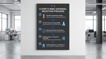
Step-by-Step Process to Specify Custom O-Rings
A systematic specification process prevents errors and ensures you get the right O-ring for your application. Each step builds on the last: groove dimensions drive size selection, operating conditions determine material choice, and validated tolerances prevent field failures.
Step 1: Measure or Design Your Groove Dimensions
Measure or design three critical groove dimensions:
- Groove ID (or OD for piston applications)
- Groove width (must accommodate O-ring OD with proper clearance)
- Groove depth (determines compression percentage)
Groove dimensions drive O-ring size selection and compression percentage. Also document groove surface finish and corner radii, as these affect seal performance and O-ring life.
Step 2: Determine Operating Conditions
Document these critical parameters:
- Operating pressure range (minimum and maximum)
- Temperature range (including startup and thermal cycling)
- Chemical exposure (all fluids, gases, cleaning agents)
- Application type (static or dynamic; if dynamic, specify reciprocating or rotary)
- Cycle frequency (for dynamic applications)
These conditions directly determine which materials qualify and which tolerances apply. With that data in hand, size and material selection becomes straightforward.
Step 3: Select O-Ring Size and Material
Size selection: Match groove dimensions with standard O-ring sizes (AS568 or metric) when possible for availability and cost. Specify custom sizes when:
- Groove dimensions don't match standard sizes
- Space constraints require non-standard cross-sections
- Performance optimization requires unique geometry
Once size is confirmed, material selection follows directly from the operating conditions documented in Step 2.
Material selection: Based on Step 2 conditions:
- Identify temperature range requirements and eliminate incompatible materials
- Compare chemical exposure against compatibility charts
- Select durometer based on operating pressure and surface finish
- Confirm static vs. dynamic suitability
- Verify regulatory certifications if required
For applications involving multiple aggressive chemicals or combined thermal and pressure extremes, material testing removes guesswork. DSC's ISO 17025 accredited lab and ISO 9001:2015 certified quality system can develop and validate custom compounds against your specific operating conditions.
Step 4: Specify Tolerances and Certifications
Tolerance selection:
- Standard tolerances (ISO 3601-1 Class B or AS568 standard): Sufficient for most general industrial applications
- Tighter tolerances (ISO 3601-1 Class A): Required for high-pressure, precision, or automated assembly applications
Required certifications: Specify based on industry requirements:
- FDA, NSF, USP for regulated industries
- PPAP, material certs for automotive and aerospace
- Surface finish and visual inspection criteria for critical applications
Step 5: Validate Design with Groove Calculations
Use O-ring groove design calculators to verify:
- Compression percentage: 15-25% for static, 8-16% for dynamic
- Groove fill: Target 75%, never exceed 85% (allows for thermal expansion and volume swell)
- Clearance gaps: Prevent extrusion based on pressure and durometer
For demanding applications, CAD modeling and finite element analysis (FEA) simulate O-ring performance under actual operating conditions before any parts go into production.
How Detroit Sealing Components Can Help
Detroit Sealing Components (DSC) brings decades of precision molded rubber experience, an ISO 17025 accredited lab supported by an ISO 9001:2015 certified quality system, and access to hundreds of compounds across all rubber types. Whether you're specifying a standard O-ring or sourcing a custom geometry for a demanding environment, DSC's technical team can match the right solution to your application.
ISO 17025 Accredited Lab and ISO 9001:2015 certified quality system for Material Validation
DSC's ISO 17025 accredited laboratory and ISO 9001:2015 certified quality system validates material compatibility for critical or complex chemical environments before production begins. When existing compounds fall short on chemical resistance, temperature range, or regulatory requirements, the lab can develop and test custom formulations — reducing field failure risk through testing protocols that meet international standards for accuracy, reliability, and traceability.
Custom O-Ring Sourcing and Design Support
DSC offers comprehensive custom capabilities including:
Design services:
- Computer-aided design (CAD) for precise dimensional control
- Finite element analysis (FEA) for performance prediction and optimization
- Reliability design verification and bench testing under actual customer conditions
Custom sourcing capabilities:
- Custom-spec O-rings from 0.5mm ID × 0.4mm CS to 1600mm ID × 50mm CS
- Non-standard cross-sections and complex geometries when standard O-rings don't fit
- Infinite-Size O-Rings technology for large-scale applications without tooling costs
- Hundreds of compounds across all rubber types (Nitrile, Viton, EPDM, Silicone, FFKM, and more)
DSC stocks and sources across the full range of international standards — AS568, ISO 3601, JIS B2401, DIN 3771, and others — ensuring interchangeability and reliable availability for your program.
Fast Turnaround and Expert Support
DSC ships nationwide from Plymouth, Michigan, with fast, cost-effective transit times that keep your production schedule on track.
The value of working with DSC's skilled technical staff includes:
- Expert guidance on material selection based on your specific operating conditions
- Sizing recommendations that optimize seal performance and cost
- Specification assistance for complex applications across diverse industries
DSC serves automotive, aerospace, oil & gas, food & beverage, healthcare, semiconductor, and general industry with proven sealing expertise. Contact DSC's engineering team to discuss your application specs and get a quote.
Frequently Asked Questions
How do I determine what size O-ring I need?
Measure your groove dimensions (ID/OD, width, depth), then select an O-ring size that achieves proper compression when installed: 15-25% for static applications, 8-16% for dynamic applications. Match to standard sizes (AS568 or ISO 3601) when possible for availability and cost.
What is the standard for O-rings?
AS568 is the most common standard in North America, defining 369 sizes with dash numbers corresponding to specific dimensions. ISO 3601 defines metric sizes used internationally. Both standards ensure interchangeability and availability, with many sizes being near-equivalent.
What tolerances should I specify for my O-ring application?
Standard tolerances per AS568 or ISO 3601 Class B suffice for most applications. Specify tighter tolerance classes (ISO 3601 Class A) only for high-pressure, precision, or automated assembly applications where consistent seal performance is critical, as tighter tolerances increase cost and lead time.
How do I choose the right O-ring material for my application?
Match material properties to your operating temperature range, chemical exposure, and application type (static vs. dynamic). Use chemical compatibility charts to cross-reference fluids with candidate materials. For complex multi-chemical environments or extreme conditions, consult a sealing specialist or submit samples for lab testing.
What's the difference between AS568 and metric O-ring sizes?
AS568 uses imperial measurements (inches) with dash numbers (-010, -214, etc.), while metric standards (ISO 3601, DIN, JIS) use millimeters. Many sizes are interchangeable due to similar cross-sections. Choose based on your industry standards, global supply chain requirements, or customer specifications.
When should I specify a custom O-ring vs. a standard size?
Standard sizes are the default choice — lower cost, faster lead times, and broad availability. Go custom when groove dimensions fall outside standard ranges, space constraints demand unique geometry, or standard sizes would require design compromises that compromise seal reliability.