Most sealing failures don’t happen because the O-ring itself is defective; they happen because small design decisions don’t hold up under real operating conditions. What seems like a minor detail during design can quickly turn into leaks, accelerated wear, and unplanned downtime once pressure, temperature, and motion come into play.
Industry studies on hydraulic systems report leakage rates ranging from ~1% to 25%, depending on system complexity and assembly conditions. This variability often traces back to how the seal is housed and supported. Poor gland geometry amplifies these risks, while well-designed glands help stabilize seal behavior across tolerances and operating ranges.
This guide explains how proper O-ring gland design improves sealing reliability, covering proven design principles, common gland types, material considerations, and practical best practices to help prevent avoidable failures in real-world applications.
Key Highlights
Most sealing failures stem from poor gland design, not bad O-rings, with leakage rates ranging from ~1% to 25% due to geometry and tolerance issues.
Squeeze, stretch, and gland fill are the core design drivers, and even small deviations can cause leaks, wear, or extrusion.
Static, dynamic, axial, and dovetail glands each require specific rules for squeeze, surface finish, and retention.
Material choice impacts gland dimensions, since elastomers vary in hardness, elasticity, and thermal expansion.
Common failures come from avoidable design and assembly errors, and Detroit Sealing Components supports engineers with the right materials, sizes, and sealing components to prevent them.
What Is an O-Ring and an O-Ring Gland?
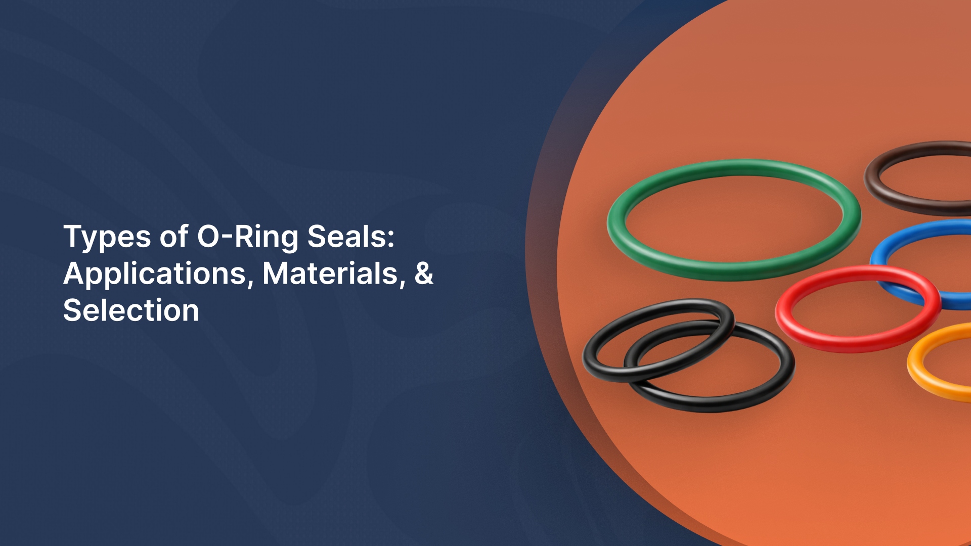
An O-ring is a circular, elastomeric sealing ring designed to prevent the passage of fluids or gasses between two mating surfaces. When compressed during assembly, the O-ring deforms elastically and creates contact stress against the sealing surfaces. This contact stress, combined with system pressure, blocks leak paths and maintains a seal across a wide range of pressures, temperatures, and media.
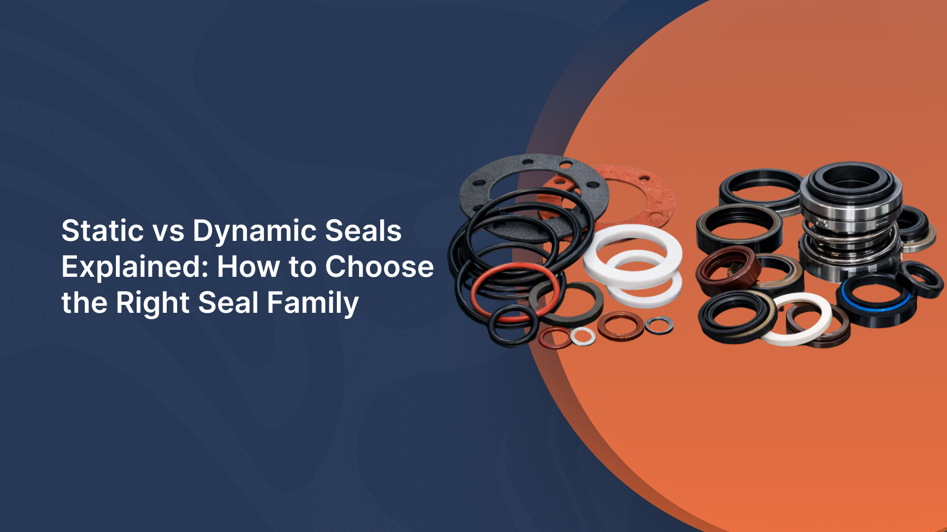
O-rings are popular because they are simple, compact, cost-effective, and versatile, working in static applications (no relative movement) as well as dynamic ones (reciprocating or rotating motion).
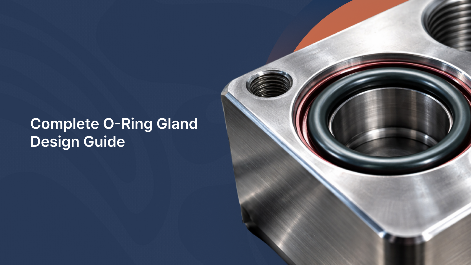
O-Ring Gland: The Sealing Environment
An O-ring gland (often called a groove) is the precisely machined cavity that houses the O-ring. The gland is not just a holder; it defines how the O-ring performs. Its dimensions control:
Squeeze (compression): how much the O-ring is deformed
Volume fill: how much space the O-ring occupies inside the gland
Clearance gaps: where extrusion or leakage can occur under pressure
When two parts come together, the gland geometry ensures the O-ring is compressed enough to seal without being overstressed. Proper gland design balances sealing force, friction, wear, and long-term durability. In practice, the gland is just as critical as the O-ring material itself, because even a perfect O-ring cannot seal reliably in a poorly designed groove.
3 Core Design Principles
O-ring performance is driven less by material alone and more by how the seal is mechanically managed. These core design principles define whether an O-ring delivers long-term sealing or fails prematurely.
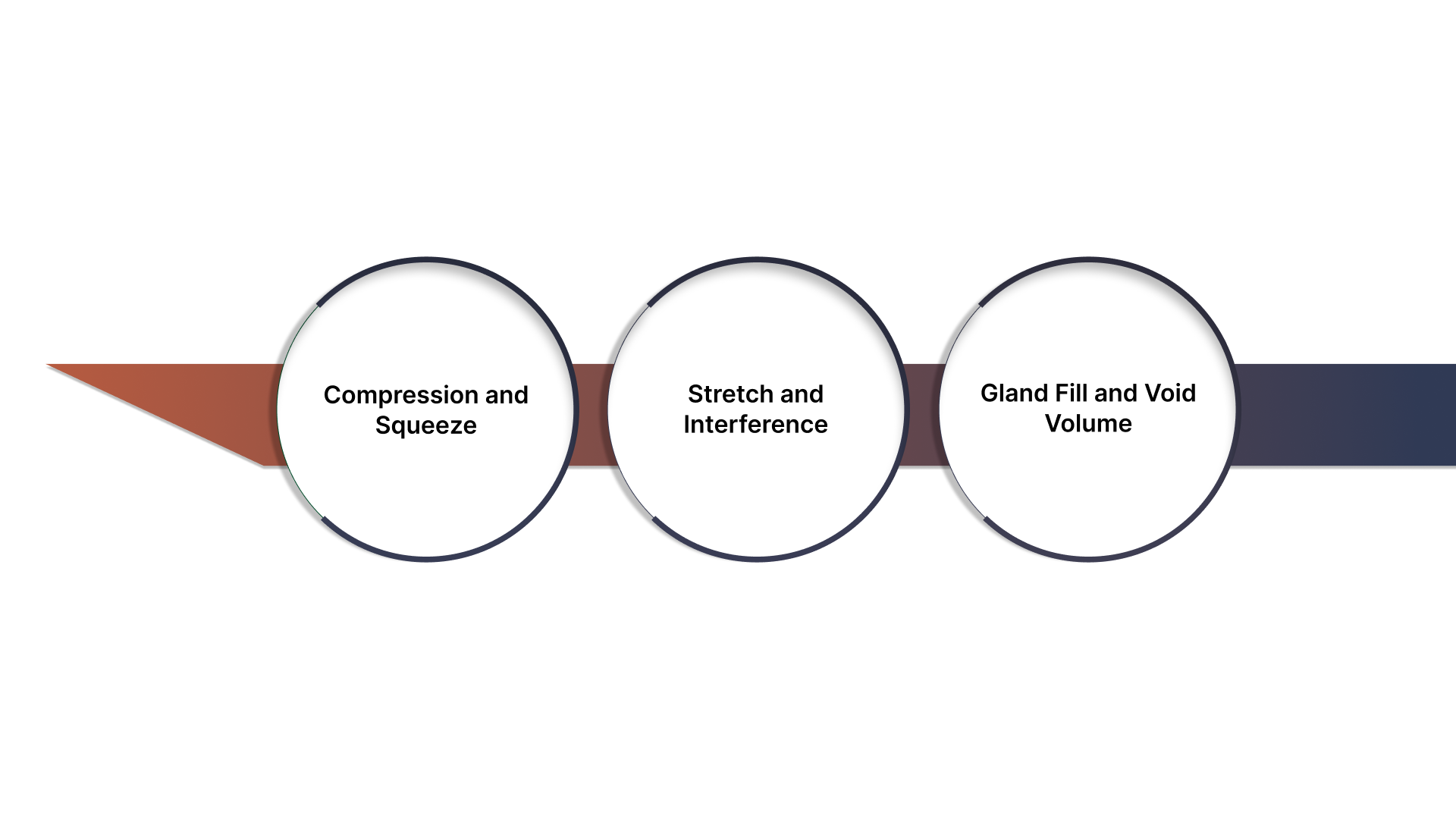
1. Compression and Squeeze
Compression is the foundation of sealing; without it, nothing else matters. Squeeze refers to the percentage of cross-section compression applied to the O-ring when installed in the gland. This deformation generates the contact stress required to block fluid or gas leakage.
Too little squeeze → insufficient contact stress, micro leak paths, pressure loss
Too much squeeze → accelerated wear, compression set, extrusion, and material cracking
Typical recommended squeeze values:
Static applications: ~15–30%
Dynamic applications: ~8–16%
Proper squeeze balances sealing force with durability.
2. Stretch and Interference
During installation, an O-ring is usually stretched slightly to fit over a shaft or into a bore. This stretch ensures proper positioning and prevents sagging or twisting inside the gland.
Recommended stretch: typically 1–5%
Excessive stretch: thins the cross-section, reduces squeeze, and overstresses the elastomer
Too much stretch weakens sealing capability and can lead to early failure, especially in dynamic or pressure-cycling systems.
3. Gland Fill and Void Volume
Gland fill is the ratio between the O-ring’s volume and the total gland volume. This relationship determines how the O-ring flows and redistributes material under compression and pressure.
Underfilled gland: unstable sealing, rolling, or twisting
Overfilled gland: no room for deformation, leading to extrusion or compression damage
Typical target fill percentages:
Static glands: ~70–85%
Dynamic glands: ~60–75%
Adequate void volume allows the O-ring to respond to pressure changes without excessive stress. Correct gland fill is critical for preventing extrusion, thermal expansion failures, and long-term material fatigue.
When applying these design principles in real systems, material choice and dimensional accuracy matter just as much as theory. Detroit Sealing Components supplies standard and custom O-rings across a wide range of elastomers, helping engineers match gland geometry to real operating conditions with confidence.
4 Standard O-Ring Gland Types
Not all O-ring glands behave the same. The type of groove selected determines how the O-ring is loaded, how it responds to pressure, and how well it survives motion, misalignment, and assembly stresses.
1. Static Radial Grooves
Static radial grooves are used where there is no relative motion between the sealing surfaces. Typical applications include housings, end caps, covers, and flanged joints. The O-ring is compressed radially between an inner and outer diameter.
Key characteristics:
Higher allowable squeeze compared to dynamic seals
Minimal wear since there is no motion
Pressure energizes the O-ring, improving sealing performance
Because motion is absent, these glands tolerate a wider design window, but excessive clearance can still cause extrusion under pressure.
2. Dynamic Radial Grooves
Dynamic radial grooves are used when one surface moves relative to the other, such as in pistons, rods, and rotating shafts. The O-ring is still compressed radially, but now must survive continuous or intermittent motion.
Design considerations include:
Lower squeeze than static glands to reduce friction and heat
Controlled gland fill to prevent rolling or twisting
Surface finish becomes critical to avoid abrasion
Dynamic applications are far less tolerant of poor geometry.
3. Face (Axial) Seal Grooves
Face (or axial) seal grooves compress the O-ring axially between two flat surfaces. These designs are common in flange joints, cover plates, and vacuum systems.
Advantages:
Simple machining
Easy inspection and replacement
Excellent sealing for low-to-moderate pressures
Limitations:
Sensitive to flange flatness and bolt load distribution
Less resistant to high pressure unless properly supported
4. Specialized Groove Types
Dovetail grooves are a specialized gland type designed to mechanically retain the O-ring during assembly, disassembly, or vertical installation. The undercut profile locks the O-ring in place.
Typical use cases:
Applications requiring frequent maintenance
Vertical or overhead assemblies
Situations where adhesive retention is undesirable
Trade-offs:
More complex machining
Increased stress on the O-ring during installation
Requires careful chamfering to avoid cutting the seal
Dovetail glands are effective retention solutions, but they demand tighter dimensional control and careful installation practices to avoid damaging the O-ring.
Fundamental Principles of O-Ring Gland Design
Gland geometry defines how an O-ring is compressed, supported, and protected throughout its service life. Even small dimensional errors in width, depth, or edge detail can turn a reliable seal into a repeat failure.
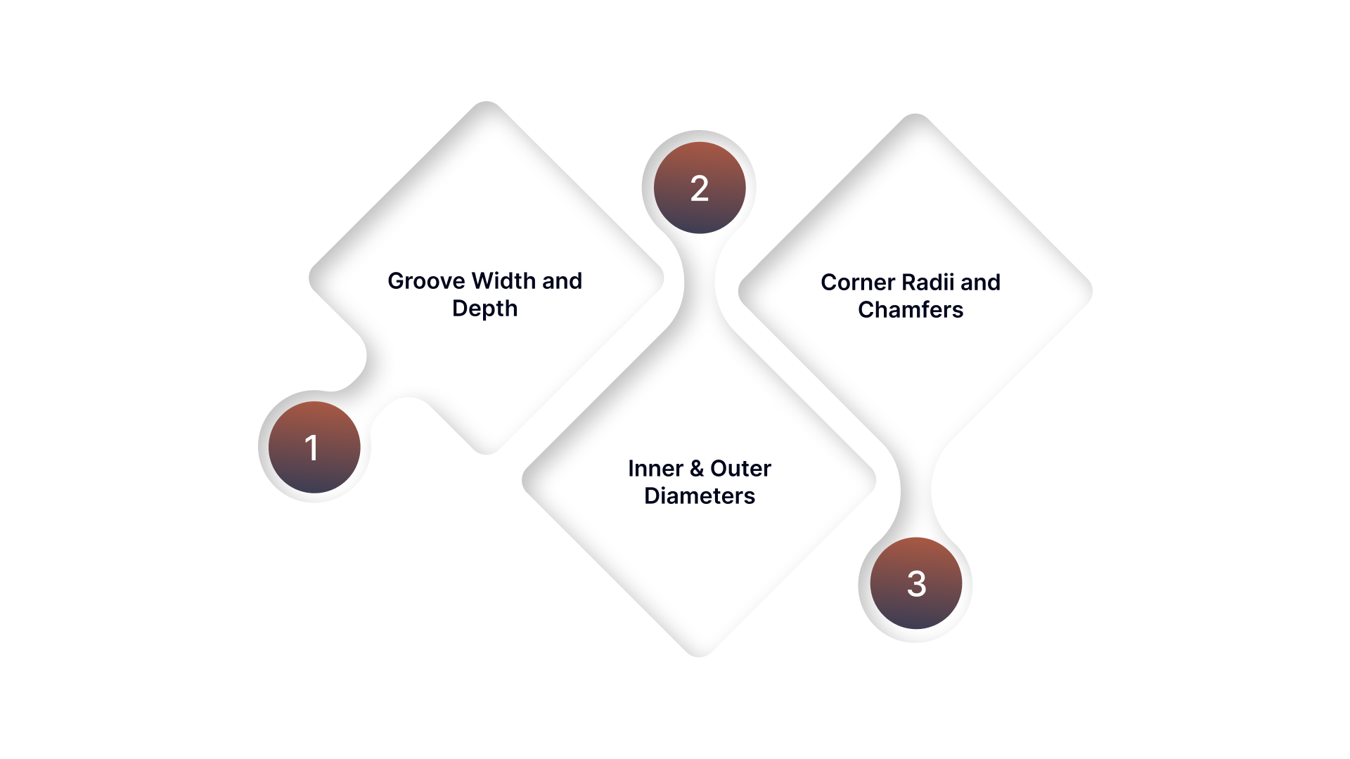
1. Groove Width and Depth
The groove depth determines how much the O-ring is compressed (squeezed), while the groove width provides room for the O-ring to expand sideways as it deforms under load and pressure.
Key guidelines:
Groove depth is selected to achieve the target squeeze based on the O-ring cross-section
Groove width must allow for material displacement without overfilling
Narrow grooves increase friction and risk extrusion
Excessively wide grooves can allow the O-ring to roll or twist
2. Inner & Outer Diameters
The inner diameter (ID) and outer diameter (OD) of the gland determine how the O-ring fits and whether it stays properly seated during operation. Correct interference ensures the O-ring remains centered and evenly loaded.
Design fundamentals:
O-rings are typically sized to stretch slightly over shafts or fit snugly in bores
Controlled stretch prevents sagging and uneven compression
Excessive interference increases assembly force and material stress
3 Corner Radii and Chamfers
Sharp edges are one of the most common and avoidable causes of O-ring damage. Corner radii and chamfers guide the O-ring into position and reduce cutting, pinching, or shaving during assembly.
Best practices include:
Adding small corner radii at groove edges to prevent stress concentrations
Using lead-in chamfers on mating components for smooth installation
Avoiding sharp transitions where the O-ring must slide or deform
Well-designed radii and chamfers not only protect the O-ring during installation but also reduce long-term abrasion in dynamic applications, directly improving seal life and reliability.
Surface Finish and Machining: Why Texture and Tooling Matter
Even a perfectly sized gland can fail if the surface it seals against is poorly finished. Surface texture directly affects leakage, friction, wear, and overall seal life, especially in dynamic applications.
1. Surface Roughness Requirements
Surface roughness is typically measured in Ra (roughness average). The required Ra value depends heavily on whether the seal is static or dynamic.
General guidelines:
Static seals: Rougher finishes are acceptable because there is no relative motion
Dynamic seals: Require smoother finishes to minimize friction, heat buildup, and abrasion
Typical recommendations:
Static applications: ~1.6–3.2 µm Ra (63–125 µin)
Dynamic applications: ~0.2–0.8 µm Ra (8–32 µin)
2. Machining Direction and Tooling Marks
Machining marks act like microscopic cutting edges when an O-ring moves across them. If these marks run perpendicular to the direction of motion, they can pump fluid past the seal or abrade the elastomer.
Best practices:
Align machining marks parallel to the direction of seal motion
Avoid spiral tool paths on shafts used in dynamic sealing
Use finishing operations (honing, polishing, grinding) where required
Even surfaces that meet Ra targets can fail if tool marks are poorly oriented. Controlled machining practices are just as important as numerical roughness values.
3. Protecting the O-Ring During Assembly and Operation
Surface quality protects the seal long before pressure is applied.
Rough edges, burrs, or chatter marks can:
Cut or nick the O-ring during installation
Accelerate wear during early operation
Create leak paths that pressure alone cannot seal
Deburring, polishing critical sealing surfaces, and inspecting for sharp transitions are essential final steps in any gland design process. When surface finish and geometry work together, O-rings deliver consistent, long-term sealing performance.
How O-Ring Material Selection Impacts Gland Design
O-ring materials do not behave the same under compression, pressure, and temperature, so gland dimensions must be adjusted to match the material’s hardness, elasticity, and long-term behavior.
NBR (Nitrile): Moderate elasticity and good compression recovery allow standard gland dimensions; higher squeeze can be tolerated in static applications, but extrusion resistance drops at elevated temperatures.
FKM / Viton®: Higher hardness and lower elasticity than NBR require slightly reduced squeeze to avoid compression set; gland fill must be carefully controlled due to lower resilience at low temperatures.
Silicone: Very soft and highly elastic, which demands lower squeeze and larger gland volume; prone to extrusion and tearing if over-compressed or used in high-pressure dynamic applications.
EPDM: Good elasticity and low compression set support standard squeeze ranges, but gland design must account for swelling when exposed to compatible fluids such as water or steam.
Polyurethane (AU/EU): High hardness and abrasion resistance require reduced squeeze and precise clearances; gland gaps must be tightly controlled to prevent stress cracking.
Hardness (Durometer) Effects: Softer compounds need more void volume and less squeeze, while harder compounds require tighter tolerances and careful extrusion gap control.
Elastic Recovery Considerations: Materials with lower rebound or higher compression set need conservative squeeze values to maintain sealing force over time.
Thermal Expansion Differences: High-temperature materials expand more, so glands must include sufficient void space to prevent overfill at operating temperature.
Material selection and gland design must always be treated as a paired decision; changing one without adjusting the other is a common cause of premature seal failure.
Because elastomer behavior directly affects gland performance, selecting the right compound is critical. Detroit Sealing Components works with leading polymer manufacturers and offers access to a wide range of elastomer materials, supporting better alignment between gland design, media compatibility, and long-term durability.
Best Practices for Manufacturing and Assembly
Manufacturing and assembly are where theoretical gland design meets reality. Small process decisions here often determine whether a seal lasts years or fails on first pressurization.
Deburr and edge-condition every sealing surface: Burrs, sharp edges, and micro-tears from machining are a leading cause of installation damage and early leakage.
Apply correct chamfer geometry: Chamfer angles and lengths should match O-ring size and hardness to prevent shaving, rolling, or spiral failure during insertion.
Use material-compatible lubrication: Proper lubricants reduce friction, ease installation, prevent twisting, and lower startup wear; incompatibility can cause swelling, softening, or chemical attack.
Control lubrication quantity: Over-lubrication can attract debris or interfere with face-seal compression, while under-lubrication increases assembly damage risk.
Maintain clean assembly conditions: Particles trapped in the gland act as leak paths and abrasion points, especially in dynamic or high-pressure systems.
Avoid stretching or twisting during installation: Excessive stretch thins the cross-section and reduces squeeze; twisting leads to uneven stress and premature failure.
Use installation tools designed for seals: Rounded, non-metallic tools prevent nicks and cuts that are invisible during assembly but catastrophic in service.
Inspect glands and O-rings together: Verify groove dimensions, surface finish, and O-ring condition as a matched system, not as separate components.
Account for assembly sequence: Press-fitting, bolt tightening order, or thermal assembly steps can alter gland compression if not planned correctly.
Train assembly personnel: Consistent results depend on repeatable handling practices, not just good drawings.
Strong manufacturing and assembly practices close the gap between design intent and real-world sealing reliability, and often deliver bigger gains than redesigning the gland itself.
Common Pitfalls and How to Avoid Them
Many O-ring failures trace back to a small set of repeat mistakes in gland design and execution. The table below highlights the most common pitfalls, their consequences, and how to prevent them.
Common Pitfall | What Goes Wrong | Impact on Sealing | How to Avoid It |
|---|---|---|---|
Over-compression | Excessive squeeze flattens the O-ring beyond its elastic range | Compression set, accelerated wear, extrusion, short seal life | Design squeeze within recommended ranges and account for tolerances and thermal expansion |
Insufficient stretch | O-ring does not seat firmly in the gland | Sagging, uneven compression, leakage at low pressure | Apply controlled stretch (typically 1–5%) and size ID/OD correctly |
Incorrect surface finish | Sealing surface too rough or improperly machined | Abrasion, leakage, high friction, and early failure | Specify Ra values based on static vs. dynamic use and control machining direction. |
Wrong groove shape | Groove depth, width, or profile is incorrect for the application | Rolling, twisting, extrusion, unstable sealing | Match groove geometry to O-ring size, material, and motion type |
Designing with these pitfalls in mind and validating against worst-case conditions eliminates many failures before they ever reach production or the field.
How Detroit Sealing Components Aligns with O-Ring Gland Design Best Practices
Detroit Sealing Components supports many of the design principles covered in this blog through its focus on elastomeric sealing solutions and application-driven product offerings.
Broad O-ring inventory: Stocks standard and custom O-rings across common size standards, supporting proper gland sizing for static and dynamic applications.
Wide material selection: Offers compounds such as NBR, FKM, EPDM, silicone, and high-performance elastomers, enabling designers to align gland geometry with material hardness, elasticity, and environmental demands.
Solutions for high-pressure sealing: Supplies back-up rings and complementary sealing components that help prevent extrusion in high-pressure glands.
Dynamic sealing alternatives: Provides X-rings (quad-rings) designed to reduce friction and resist twisting, directly addressing challenges in dynamic radial grooves.
Custom molding capability: Supports application-specific sealing needs where standard gland designs or sizes are insufficient.
Technical resources: Offers downloadable guides and reference material that reinforce best practices for seal selection, sizing, and performance validation.
Detroit Sealing’s product range and technical focus directly complement sound O-ring gland design, reinforcing the principle that reliable sealing depends on matching geometry, material, and operating conditions as a complete system.
Conclusion
Reliable O-ring sealing comes from getting the fundamentals right, gland geometry, material selection, tolerances, surface finish, and validation under real operating conditions. The O-ring itself does not cause most seal failures, but by avoidable design and assembly issues. Applying proven gland design principles early leads to longer seal life, fewer leaks, and more dependable system performance.
For expert support with O-ring selection, custom sealing solutions, and components designed to match real-world gland requirements, Detroit Sealing Components is a trusted resource.
Contact Detroit Sealing Components to discuss your application and get guidance on building reliable, leak-free sealing solutions.
FAQ
1. How much squeeze should an O-ring have?
Proper squeeze depends on the application. Static seals typically require higher squeeze than dynamic seals, but excessive compression can cause premature wear, extrusion, or compression set.
2. When should a back-up ring be used?
Back-up rings are recommended for high-pressure applications, large clearance gaps, or soft elastomers. They prevent O-ring extrusion into gaps that can cause nibbling and seal failure.
3. Does surface finish really affect sealing performance?
Yes. Rough or poorly oriented machining marks can abrade the O-ring or create leak paths. Dynamic seals require smoother surface finishes than static seals to reduce friction and wear.
4. Can the same gland design be used for different O-ring materials?
Not always. Different materials vary in hardness, elasticity, and thermal expansion, which often requires adjustments to squeeze, gland fill, and clearance.
5. Why is worst-case tolerance design important?
Because real parts are never nominal. Designing for tolerance stack-up ensures the seal performs reliably even at maximum and minimum dimensional limits.