O-ring “compression” is one of those terms that sounds simple until a seal leaks, even though the size and material seem right. Many leaks trace back to installed squeeze, clearance support, and friction conditions, not the material callout on the box.
They’re about whether the O-ring is being squeezed the way the hardware was designed to squeeze it and whether pressure, motion, and clearance gaps are undoing that seal.
This guide shows you how to think about O-ring compression the practical way: what it actually means, what controls it in the gland, and how to sanity-check it fast so you can stop guessing and stop repeating the same leak cycle.
Key Takeaways
O-ring compression (squeeze) is the controlled deformation set by the gland/groove that creates sealing force. Squeeze ≠ compression set (compression set is a permanent flattening over time).
Squeeze comes from gland depth vs O-ring cross-section, not “tightening harder.”
Targets change with static vs dynamic sealing and with pressure spikes + clearance gap (extrusion risk).
If it’s leaking, check under-squeeze, over-squeeze/pinch, or extrusion before swapping materials.
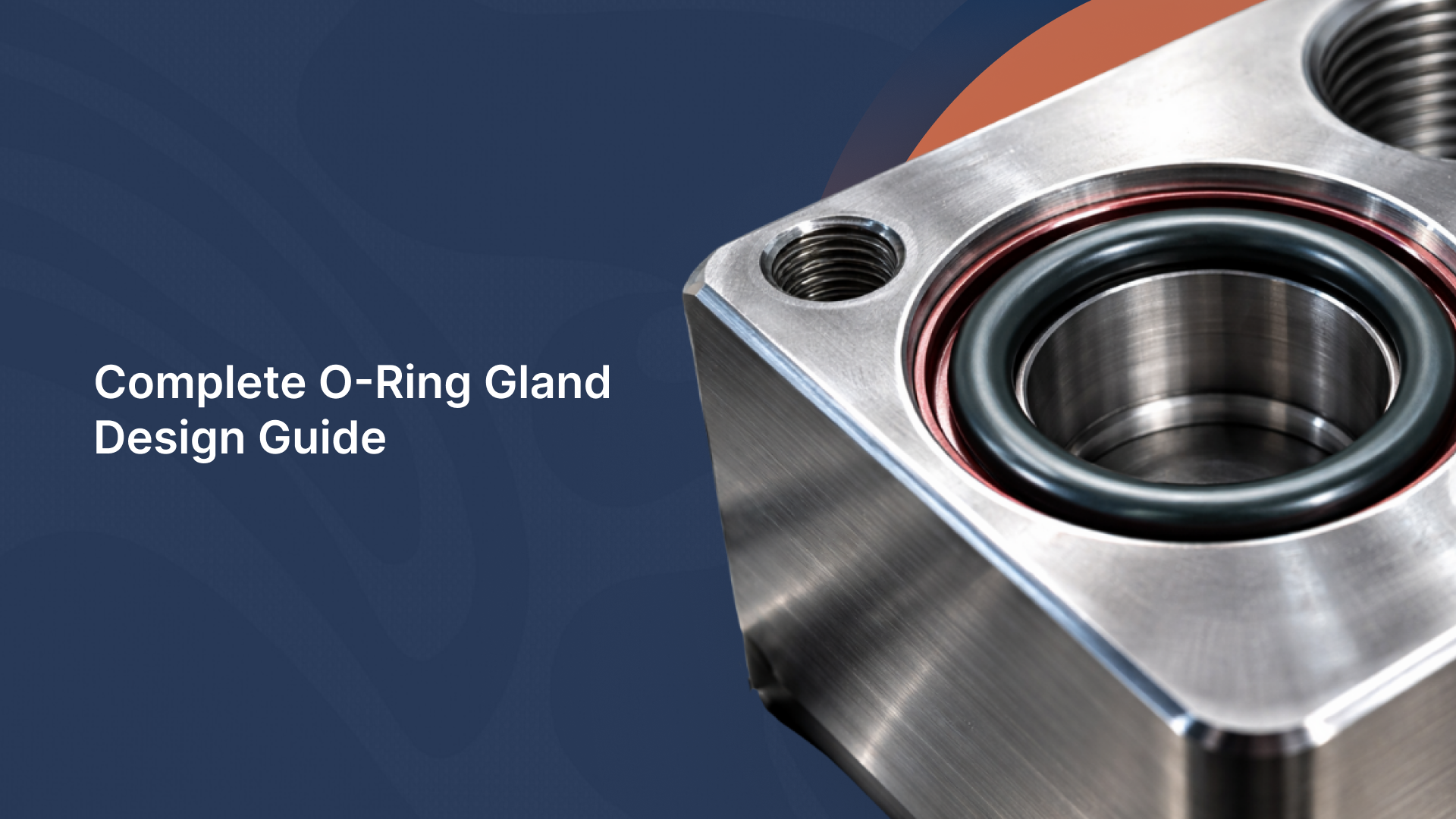
What “O-ring compression” means
When people search “O-ring compression,” they’re usually talking about squeeze: the intentional amount the O-ring is flattened when installed. That controlled deformation is what creates sealing force and lets the rubber conform to small surface imperfections.
The term that gets confused with squeeze is compression set. Compression set is not how much the O-ring is squeezed during assembly; it’s the permanent loss of rebound after time in service (heat + time + chemistry + over-squeeze).
A seal with a high compression set can look “fine,” but it won’t push back and maintain sealing force, so leaks show up later.
Why this matters: wrong squeeze causes predictable problems, too little squeeze leaks, too much squeeze pinches/cuts and drives friction heat in dynamic use, and with pressure + clearance it can accelerate extrusion/nibbling even if the material is “rated.”
The geometry that sets the squeeze
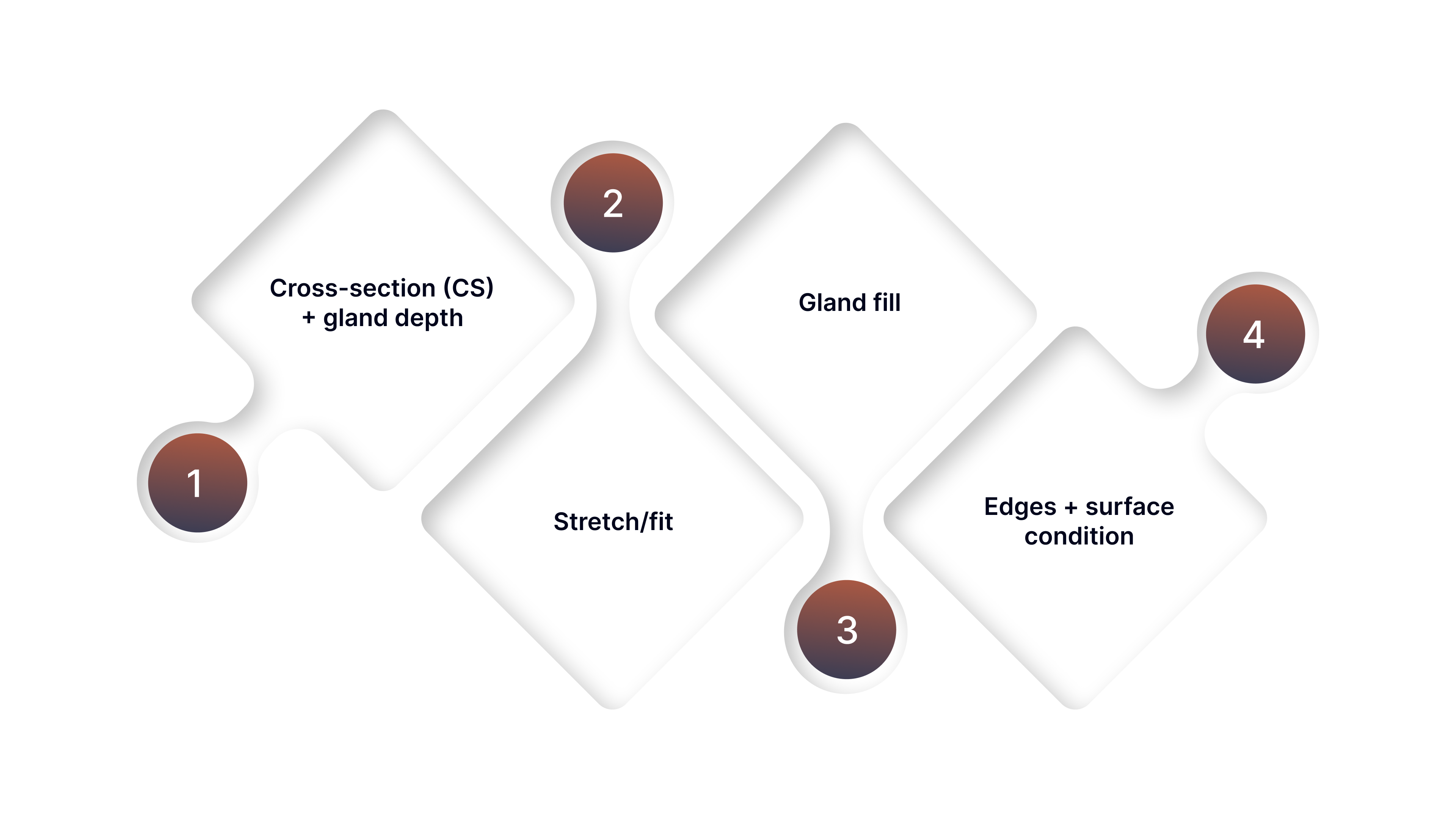
O-ring “compression” (squeeze) is baked into the hardware geometry. If you want predictable sealing, these are the only inputs that actually set squeeze:
Cross-section (CS) + gland depth (the core relationship)
CS is the O-ring’s thickness; gland depth is how much space you give it. When the parts close, the difference between CS and gland depth is what creates the squeeze. If the groove is too deep, you under-squeeze and leak. If it’s too shallow, you over-squeeze and risk pinching, high friction, and early wear.
Stretch/fit (how ID fit quietly changes CS and squeeze)
If you stretch an O-ring onto a larger diameter, the rubber “necks down” slightly, CS gets thinner, which reduces the squeeze even if the groove was correct. That’s why two rings with the “same CS on paper” can seal differently if one is over-stretched in assembly.
Gland fill (why “almost the same CS” isn’t close)
Small CS differences change how much volume the O-ring occupies in the groove. Too much fill can cause pinching and assembly damage; too little fill can allow movement/rolling in dynamic service. This is the hidden reason “close enough” sizes often fail.
Edges + surface condition (how sharp details defeat ‘correct’ squeeze)
A perfect squeeze number won’t survive sharp lead-ins, burrs, thread edges, or rough finishes. Those create cuts/nicks during assembly and turn “correct geometry” into immediate leaks. Clean chamfers, deburring, and a sane surface finish are part of squeeze reliability.
Once the geometry is understood, the only remaining question is: what squeeze range fits your duty?
Squeeze targets by application
Use these typical starting ranges (percent of O-ring cross-section, CS) as a fast lookup. They’re not universal; compound/durometer, temperature, groove fill, and pressure spikes can shift what’s “right,” but they’re solid screening targets for most designs.
These ranges are general guidance; confirm your final gland dimensions and squeeze targets against your OEM drawing/spec and the applicable standard (e.g., AS568/ISO 3601) for your compound, duty cycle, and application.
Application | Typical squeeze goal (range) | Why that range works | What to verify |
|---|---|---|---|
Static face seal (covers/flanges) | 20–30% | Higher squeeze helps tolerate minor flatness/finish variation and seals without motion wear. | Surface finish/flatness, bolt load consistency, groove depth uniformity, groove fill (avoid overfill). |
Static radial (piston/bore) | 10–20% | Enough squeeze to seal radially without excessive assembly force or high friction. | Bore finish, diametral clearance, piston/bore concentricity, O-ring stretch (don’t thin CS). |
Static radial (rod/shaft) | 10–20% | Similar to piston/bore: stable sealing force without unnecessary drag. | Rod finish, eccentricity/misalignment, extrusion gap at pressure, lead-in chamfers (install damage). |
Reciprocating dynamic (rod/piston) | 8–16% | Lower squeeze reduces friction/heat and rolling/twist risk while still maintaining sealing force. | Lubrication plan + compatibility, surface finish, side load/misalignment, spiral/twist evidence, groove fill. |
Rotary dynamic (shaft rotation) | 6–12% (O-ring often not ideal as the primary rotary seal) | Rotary duty is heat/runout sensitive; lower squeeze helps reduce frictional heat. | Shaft runout/misalignment, surface speed/heat, lubrication, and whether a rotary lip seal is the better primary choice. |
High pressure/pressure spikes present | Use the “base” range above (then control extrusion) | At high pressure, failures are often extrusion/clearance-driven; more squeeze won’t fix a gap. | Extrusion gap under load, spike magnitude, back-up ring need/placement, and groove support on the low-pressure side. |
Vacuum / very low pressure sensitivity | 20–30% (often) | Little/no pressure-assist—seal depends heavily on initial squeeze and surface conformity. | Surface finish, outgassing/compatibility if applicable, leak path control (scratches), and consistent squeeze around the full circumference. |
Now you have the target; here’s how to confirm your hardware actually produces it.
Quick squeeze check in the real world
Even with the “right” O-ring and gland style, leaks usually come from one of two things: the hardware isn’t producing the intended squeeze, or the old O-ring you measured wasn’t a trustworthy reference. This is the fastest way to sanity-check the squeeze before you start changing materials or sizes.
What to measure
O-ring cross-section (CS): measure in 3–4 spots and use the most consistent value.
Gland depth: measure the groove depth where the O-ring sits (clean the groove first).
Don’t trust the old O-ring if it’s swollen, gummy, cracked, or has a clear flat from compression set; use the gland/drawing as the reference instead.
Quick calculation
Squeeze (inches or mm) = CS − gland depth
Squeeze % = (CS − gland depth) ÷ CS × 100
That’s enough math to tell if you’re in the right ballpark; no need to build a full gland design model for a field check.
Sanity checks
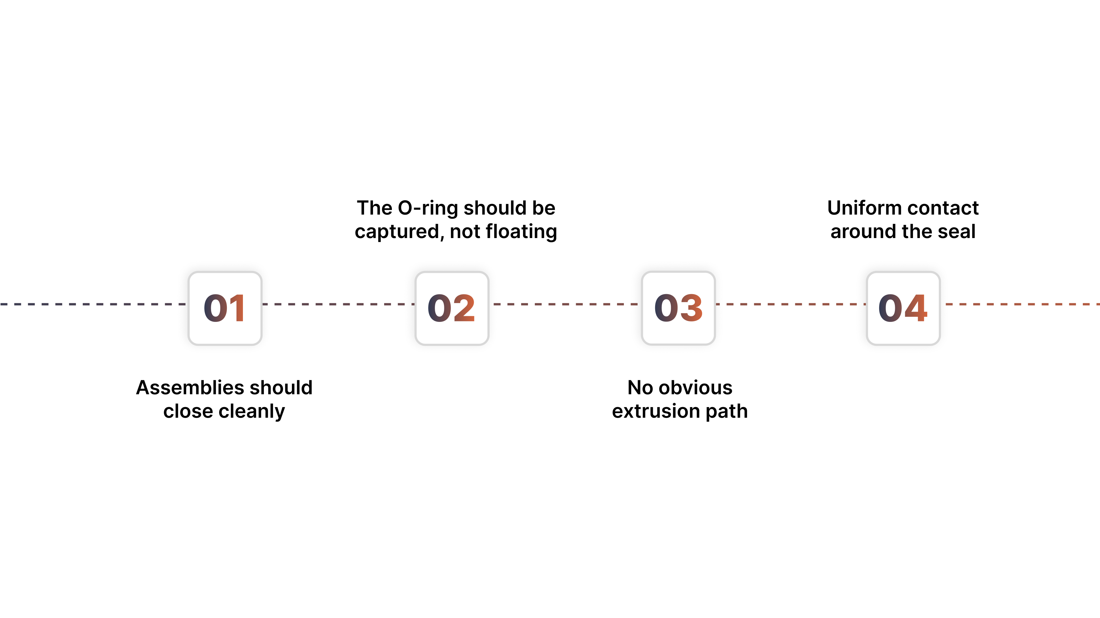
Assemblies should close cleanly: no shaving, pinching, or “cuts on entry.” If you’re forcing it, you’re likely over-squeezing or hitting sharp edges.
The O-ring should be captured, not floating: if it can move/roll in the groove before assembly, expect twist, uneven wear, or leaks in dynamic service.
No obvious extrusion path: if you can see/feel a clearance gap where pressure will push the seal, plan extrusion control (support or back-up), not “harder rubber.”
Uniform contact around the seal: uneven squeeze often points to warped faces, poor concentricity, or misalignment.
When to switch references
If the removed O-ring shows flattening, swelling, hardening, or nicks, treat its dimensions as a failure artifact. Use the gland dimensions, drawings, or a known standard size to confirm what the seal should be.
If the geometry and squeeze check out, the next failures are almost always driven by operating conditions, pressure spikes/clearance, motion/friction heat, media incompatibility, or installation damage.
What changes the “right” squeeze once the system is running
A squeeze that looks perfect on the bench can behave very differently once pressure, motion, and temperature enter the picture. These operating factors modify what “right” looks like in service, and they explain why some seals fail even when the squeeze math checks out.
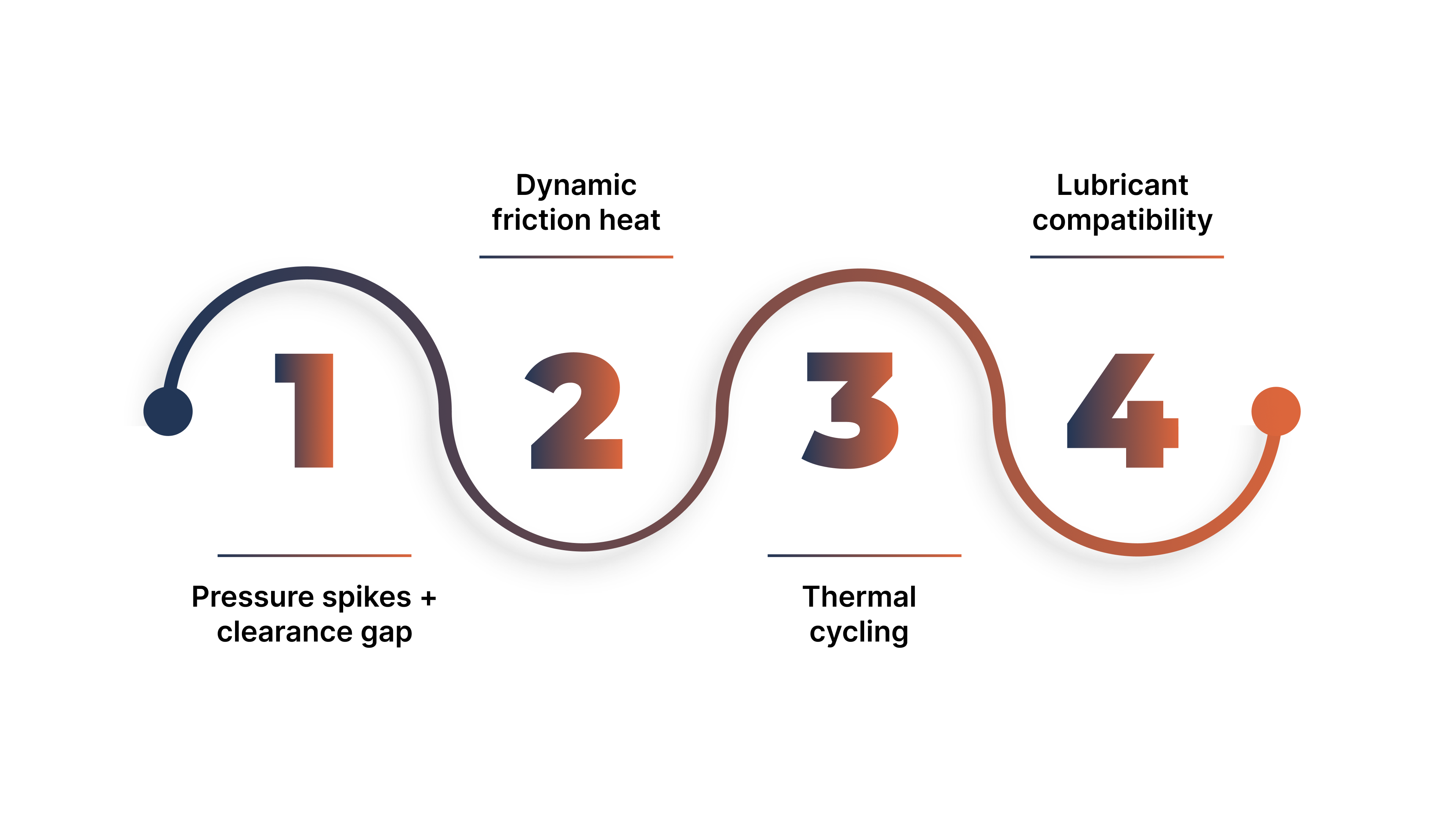
Pressure spikes + clearance gap
Even with “correct squeeze,” pressure will try to push the O-ring into any open clearance path. When spikes hit, that force rises fast so the seal can extrude and nibble (chewed edge, missing bites) despite an otherwise reasonable gland.
What this means in practice: if spikes + gap exist, reliability comes from support/containment (tight clearance, back-up ring, or a different seal family), not just changing squeeze.
Dynamic friction heat
In dynamic service, the O-ring is not just sealing; it’s rubbing. That creates localized heat and wear.
More squeeze usually means more friction, which can accelerate wear, generate heat, and trigger stick-slip.
Dynamic setups often need controlled (often lower) squeeze, better lubrication, and sometimes a different seal style (e.g., X-ring/energized seals) depending on duty.
Thermal cycling
Heat and cold change dimensions and rubber behavior over a cycle.
At high temperatures, elastomers soften and can become more extrusion-prone, while long exposure can drive compression set (loss of rebound).
At low temperatures, compounds stiffen and may not conform well at startup, creating cold-start weeping until things warm up.
The key point: you’re not designing for a single temperature, you’re designing for the worst-case point in the cycle.
Lubricant compatibility
Lubrication can make a good squeeze behave like a bad one fast.
Wrong or incompatible lube can cause swelling/softening, stick-slip, or accelerated wear.
No lube (when the application needs it) can turn an acceptable squeeze into heat + abrasion and early failure.
Rule: lube has to match compound + media + temperature
When the squeeze is off in service, the failure signature is usually obvious if you know what to look for.
Failure signatures that point to a squeeze problem
Squeeze-related failures are usually diagnosable from the symptom timing and what the seal looks like after removal. Use the pattern that matches your case and apply the first fix before changing compound, hardness, or seal style.
Immediate leak, O-ring looks normal (no cuts, no chewed edge)
What it usually means: under-squeeze, wrong cross-section (CS), wrong standard (inch vs metric), or the O-ring isn’t being captured/controlled.
First fix: re-check CS and standard, then confirm the gland depth is producing enough squeeze for that CS. If the ring is worn/flattened, use the gland/drawing dimensions as the reference.
Leak + visible pinch, slice, or shaved section right after assembly
What it usually means: over-squeeze, sharp edges/threads, poor lead-in, or the ring is being trapped and cut during assembly.
First fix: add/verify lead-in chamfers and deburr edges; confirm correct CS for the gland; use a compatible assembly lubricant; avoid twisting and over-stretching during install.
Chewed edge / “bites missing” / ragged material on one side (nibbling/extrusion)
What it usually means: pressure is pushing the O-ring into a clearance gap, often worsened by spikes or thermal softening.
First fix: reduce the extrusion gap or add extrusion support (back-up ring) in the correct pressure direction; verify spike magnitude and where the gap opens under load.
Rapid wear, glazing, heat marks, or early leakage in dynamic motion
What it usually means: friction and surface interaction are dominating (too much squeeze for the duty, poor lubrication, surface finish mismatch, side-load/misalignment).
First fix: verify lubrication compatibility and supply; confirm surface finish is appropriate for the motion; reduce friction drivers (squeeze, side-load) and validate alignment/runout.
Leaks develop later after time-in-service (often without dramatic visible damage)
What it usually means: compression set/aging, thermal cycling effects, or chemical exposure, reducing rebound and sealing force.
First fix: confirm the real temperature profile (continuous vs peaks), full exposure list (including cleaners), and whether the joint can tolerate loss of rebound; adjust compound selection and service interval based on duty cycle.
When you match the failure signature to the right first fix (squeeze/geometry, installation, extrusion support, or friction control), you can start with the check that’s most likely to change the outcome.
Dynamic Sealing Options Detroit Sealing Components Supports
If you’re working through an O-ring “compression” problem, the fastest progress usually comes from confirming what’s actually limiting sealing in your setup: squeeze (under/over), extrusion support (clearance + spikes), or friction/wear (motion + surface + lube).
Detroit Sealing Components can support that full decision path so you’re not stuck trying random cross-sections or “harder rubber” when the hardware or duty cycle is the real constraint.
Get squeezed right (fit validation, not guesswork)
DSC can help verify whether your cross-section (CS) and gland depth are producing a sane squeeze range for your application, and whether the issue is under-squeeze (leak) or over-squeeze (pinch/cut/friction), especially when the old O-ring is flattened, swollen, or otherwise untrustworthy as a measurement reference.
Stability in motion (when the squeeze becomes inconsistent)
In reciprocating/dynamic applications where O-rings tend to roll, twist, or wear unevenly, DSC can supply X-rings/quad-rings as a common step-up option. These profiles are often used when the problem isn’t “insufficient squeeze,” but instability under motion that makes the sealing line unreliable.
Extrusion control (when squeeze alone can’t beat spikes + clearance)
If pressure spikes and an extrusion gap are present, squeeze can look “correct” and still fail by nibbling/extrusion. DSC can provide back-up rings to support the O-ring and block extrusion into the clearance path, often the difference between repeated edge-chew failures and a stable seal.
High-duty motion (when an O-ring isn’t the reliability path)
For high-cycle cylinders/actuators or demanding dynamic duty, reliability often comes from purpose-built hydraulic/dynamic seals (plus the right exclusion strategy) rather than pushing O-rings harder.
DSC supports hydraulic/dynamic seals for cases where wear control, leakage control, and contamination tolerance are the real requirements.
Send ID + CS, gland depth/geometry (or a drawing), motion type, and pressure + spikes, and Detroit Sealing Components can help confirm the right squeeze strategy and whether you need an O-ring, X-ring, back-up ring, or a dynamic seal family for reliable performance.
Conclusion
Reliable O-ring sealing isn’t about chasing a magic “compression” number it’s about controlling three things as a system: the installed squeeze your gland actually produces, the extrusion risk created by clearance gaps and pressure spikes, and the friction/heat generated by motion and surface/lubrication then verifying all three against your real duty cycle (pressure behavior, temperature swings, and time-in-service) so the seal holds up beyond the first assembly.
FAQs
What is O-ring compression (squeeze)?
O-ring “compression” usually means squeeze: the intentional amount the O-ring is flattened in the gland when installed. That controlled deformation creates sealing force and helps the rubber conform to small surface imperfections.
What percent should an O-ring be compressed?
It depends on the application and motion. Static seals typically tolerate more squeeze than dynamic seals (which usually need less to control friction/heat). Use the “Squeeze targets by application” table as your starting range, then confirm your gland actually produces it.
What’s the difference between squeeze and compression set?
Squeeze is the planned, installed deformation. Compression set is what happens over time; the O-ring permanently loses rebound (often due to heat, time, chemistry, or excessive squeeze) and stops maintaining sealing force, which can cause leaks later.
What happens if an O-ring is over-compressed?
Over-squeeze commonly leads to pinching/cuts on assembly, high friction/heat in dynamic use, accelerated wear, and sometimes extrusion damage if pressure forces the overfilled seal into a clearance gap.
What happens if an O-ring is under-compressed?
Under-squeeze typically causes immediate leakage or weeping (especially at low pressure or vacuum) because the seal doesn’t develop enough initial sealing force or surface conformity often tied to too-deep gland, wrong CS, or inch/metric near-miss sizes.